MR-E Super Servomotors and Amplifiers
Сопутствующее оборудование - Контроллеры FX1N/2N/2NC
|
Код для заказа |
Иллюстрация |
Модель |
Описание |
|
43393 |
|
SC09 |
Кабель-конвертер RS232C/RS422 для соединения PC и ПЛК MELSEC (FX, A(nSH) и QnA(S)), 3 м |
|
165288 |
|
FX-USB-AW |
Кабель-конвертер USB/RS422 для соединения PC и ПЛК MELSEC (FX), 3м |
|
139418 |  |
FX1N-4EX-BD |
Интерфейсный адаптер; 4 цифр. входа; для FX1S и FX1N |
|
139420 |
FX1N-2EYT-BD |
Интерфейсный адаптер; 2 цифр. выхода; для FX1S и FX1N | |
|
139421 |
|
FX1N-2AD-BD |
Интерфейсный адаптер;2 аналог. входа;12 bit для FX1S и FX1N |
|
139422 |
FX1N-1DA-BD |
Интерфейсный адаптер;1 аналог. выход;12 bit для FX1S и FX1N | |
|
130743 |
|
FX1N-232-BD |
Встраиваемый модуль:RS-232 - интерфейс; |
|
130741 |
|
FX1N-422-BD |
Встраиваемый модуль:RS-422 - интерфейс; |
|
130742 |
|
FX1N-485-BD |
Встраиваемый модуль:RS-485 - интерфейс; |
|
65596 |
|
FX2N-232-BD |
Встраиваемый модуль:RS-232 - интерфейс; |
|
65595 |
|
FX2N-422-BD |
Встраиваемый модуль:RS-422 - интерфейс; |
|
65597 |
|
FX2N-485-BD |
Встраиваемый модуль:RS-485 - интерфейс; |
|
130745 |
|
FX1N-CNV-BD |
Специальный коммуникационный адаптер FX1S и FX1N для FX0N и FX2N/FX2NC |
|
65598 |
FX2N-CNV-BD |
Специальный коммуникационный адаптер для FX0N/FX2N | |
|
70880 |
|
FX2N-CNV-BC |
Разъем для подключения модулей расширения кабелем FX0N-65EC |
|
104508 |
|
FX2NC-CNV-IF |
Специальный коммуникационный адаптер для FX2N, FX0N или FX |
|
130746 |
|
FX1N-EEPROM-8L |
Кассета памяти EEPROM; 8000 steps PLC program; with FX1S/FX1N |
|
23826 |
FX-EEPROM-8 |
Кассета памяти EEPROM; 8000 steps PLC program; with FX2N | |
|
65600 |
FX-EEPROM-16 |
Кассета памяти EEPROM; 16000 steps PLC program; with FX2N | |
|
141528 |
FX2N-ROM-E1 |
Кассета памяти 16K EEPROM, с переключателем разрешения записи; для FX2N | |
|
104507 |
FX2NC-EEPROM-16 |
Кассета памяти 16K steps EEPROM с переключателем разрешения записи; | |
|
149016 |
FX2NC-ROM-EC1 |
Кассета памяти 16K steps EEPROM с переключателем разрешения записи; часы реального времени, | |
|
137206 |
|
FX2NC-RTC |
Адаптер для часов реального времени для FX2NC |
|
56173 |
|
CR01-R4/R4 |
Преобразователь интерфейса RS422 and RS422; опторазвязка |
|
56172 |
|
CR01-R2/R4 SET |
Преобразователь интерфейса RS232/RS422 and RS422; опторазвязка |
|
3386 |
|
Switch-Box |
Иммитатор срабатывания дискретных сигналов (12 переключателей) |
|
66513 |
Input-SIM: FX2N |
Иммитатор срабатывания дискретных сигналов (8 переключателей) | |
|
65081 |
Input-SIM: FX1S/FX1N |
Иммитатор срабатывания дискретных сигналов (8 переключателей) | |
|
210092 | 
|
FX1N-BAT |
Батарея для MELSEC FX1N |
|
5142 |
F2-40BL |
Батарея для MELSEC FX/FX2N | |
|
128725 |
FX2NC-32BL |
Батарея для MELSEC FX2NC | |
|
128731 |
|
E-GMC-200CAB |
Кабель FX2N-XXGM --> MR-C (XX = 10 oder 20) |
|
125583 |
|
E-GMJ2-200CAB1A |
Кабель FX2N-XXGM --> MR-J2 |
|
130450 |
|
E-GM-200CAB |
Кабель FX2N-XXGM --> многофункц. (XX = 10 oder 20) |
|
125189 |
|
FX-16E-TB/UL |
Клеммная колодка 16 I/O |
|
128724 |
|
FX-32E-TB/UL |
Клеммная колодка 32 I/O |
|
125584 |
|
FX-16E-150CAB |
Кабель 1,5 m FX2N-XXGM --> в клеммную колодку (XX = 10 oder 20) |
|
128722 |
FX-16E-300CAB |
Кабель 3 m FX2N-XXGM --> в клеммную колодку (XX = 10 oder 20) | |
|
130451 |
FX-16E-500CAB |
Кабель 5 m FX2N-XXGM --> в клеммную колодку (XX = 10 oder 20) | |
|
128723 |
|
FX-16E-500CAB-S |
Кабель 5 m FX2N-XXGM --> внешние у-ва (XX = 10 oder 20) |
|
149148 |
|
TB-20-S |
Клеммная колодка, 20 pin., витовой клемник |
|
149023 |
TB-20-C |
Клеммная колодка, 20 pin., защелк. соеденение | |
|
149038 |
|
TB-EX-CAB-1M |
Кабель 1 m для терминальной колодки TB-EX / TB-20 |
|
149039 |
TB-EX-CAB-3M |
Кабель 3m для терминальной колодки TB-EX / TB-20 | |
|
149040 |
TB-EX-CAB-5M |
Кабель 5m для терминальной колодки TB-EX / TB-20 | |
|
45348 |
|
FX0N-65EC |
Кабель соединения базового блока и модулей расш-я MELSEC FX0N/FX2N; 0.65 m |
|
31870 |
|
FX-20P-CADP |
Кабель-адаптер для MELSEC FX0S/FX0N/FX2N/FX2NC и периферийных устройств MELSEC FX; разъём D-SUB 25 -> miniDin 8; 0.3 м |
|
248245 |
|
FX-20P-CAB0 |
Кабель FX0S/FX0N/FX2N/FX2NC и FX-10P-E/FX-20P-E-SET0/FX-10DM-E; 3 m |
|
104509 |
|
FX2NC-100MPCB |
Кабель питания для FX2NC, 1 m |
|
104510 |
|
FX2NC-100BPCB |
Кабель к источнику питания для модулей FX3UC/FX2NC, 1 m |
|
129197 |
|
FX1N-5DM |
Дисплейный модуль для FX1S и FX1N |
|
132600 |
|
FX-10DM-E |
Панель управления и отображения MELSEC FX1S/FX1N/FX2N |
|
149036 |
|
TB-CON10-C |
Коннектор для модулей расш-я FX2NC, 10 pin |
|
149144 |
|
TB-8EX-S |
Клеммник для внешних сигналов 8 входов, винтовое соединение |
|
149145 |
TB-8EX-C |
Клеммник для внешних сигналов 8 входов, защелк. соеденение | |
|
149021 |
TB-16EX-S |
Клеммник для внешних сигналов 16 входов, винтовое соединение | |
|
149022 |
TB-16EX-C |
Клеммник для внешних сигналов 16 входов, защелк. соеденение | |
|
149044 |
|
TB-8EY-S |
Терминальная колодка для 8 выходов; гнезда для реле или транз, винтовое соединение |
|
149045 |
TB-8EY-C |
Терминальная колодка для 8 выходов; гнезда для реле или транз, защелк. соеденение | |
|
149041 |
|
TB-EY-CAB-1M |
Соединительный кабель 1 m для TB-EY |
|
149042 |
TB-EY-CAB-3M |
Соединительный кабель 3 m для TB-EY | |
|
149043 |
TB-EY-CAB-5M |
Соединительный кабель 5 m для TB-EY | |
|
149034 |
|
TB8-RELAY-6A |
Выносной блок для 8 реле 6A; для TB-8EY и ST16-SOCKET |
|
149035 |
TB8-TRANSISTOR-2A |
Выносной блок для 8 транзисторов 2A; для TB-8EY и ST16-SOCKET | |
|
149146 |
|
TB-PIB-RD |
Аксессуар для колодок TB, шлейф 500 mm; для TB-8EY, красный |
|
149147 |
|
TB-PIB-BL |
Аксессуар для колодок TB, шлейф 500 mm; для TB-8EY, синий |
|
149158 |
|
TB-SP |
Аксессуар для колодок TB, разделительная пластина для TB-8EY |
|
221271 |
|
FX-30P |
Ручной программатор для серии FX |
Сопутствующее оборудование - Контроллеры FX1S
|
Код для заказа |
Иллюстрация |
Модель |
Описание |
|
43393 |
|
SC09 |
Кабель-конвертер RS232C/RS422 для соединения PC и ПЛК MELSEC (FX, A(nSH) и QnA(S)), 3 м |
|
165288 |
|
FX-USB-AW |
Кабель-конвертер USB/RS422 для соединения PC и ПЛК MELSEC (FX), 3 м |
|
139418 |
|
FX1N-4EX-BD |
Интерфейсный адаптер; 4 цифр. входа; для FX1S и FX1N; Note: использовать только совместно с фирменным софтом 2.00! Для FX1S/FX1N |
|
139420 |
FX1N-2EYT-BD |
Интерфейсный адаптер; 2 цифр. выхода; для FX1S и FX1N; Note: использовать только совместно с фирменным софтом 2.00! Для FX1S/FX1N | |
|
139421 | 
|
FX1N-2AD-BD |
Интерфейсный адаптер;2 аналог. входа;12 bit для FX1S и FX1N; |
|
139422 |
FX1N-1DA-BD |
Интерфейсный адаптер;1 аналог. выход;12 bit для FX1S и FX1N; | |
|
130743 |
|
FX1N-232-BD |
Встраиваемый модуль:RS-232 - интерфейс; |
|
130741 |
|
FX1N-422-BD |
Встраиваемый модуль:RS-422 - интерфейс; |
|
130742 |
|
FX1N-485-BD |
Встраиваемый модуль:RS-485 - интерфейс; |
|
130745 |
|
FX1N-CNV-BD |
Коммуникационный адаптер для FX1S и FX1N, для FX0N и FX2N/FX2NC исп. спец. модуль |
|
130744 |
|
FX1N-8AV-BD |
Аналоговый задатчик установок для FX1S |
|
130746 |
|
FX1N-EEPROM-8L |
EEPROM кассета памяти; 8000 steps PLC program; для FX1S/FX1N |
|
129197 |
|
FX1N-5DM |
Дисплейный модуль для FX1S и FX1N |
|
132600 |
|
FX-10DM-E |
Панель управления и отображенияr MELSEC FX1S/FX1N/FX2N |
|
3386 |
|
Switch-Box |
Приставка имитации состояния цифровых входов (12 переключателей) |
|
65081 |
Input-SIM: FX1S/FX1N |
Приставка имитации состояния цифровых входов (8 переключателей) | |
|
149109 |  |
FX-20P-E-SET0 |
Ручной программатор с RAM и кабелем FX-20P-CAB0 |
|
23819 |
FX-20P-ADP |
Адаптер питания для программатора FX-20P-E |
Сопутствующее оборудование - Контроллеры ALPHA XL
|
Код для заказа |
Иллюстрация |
Модель |
Описание |
|
142528 |
|
AL2-GSM-CAB |
Кабель для соединения AlphaXL с GSM модемом |
|
231365 |
|
AL2-FRAME-10-IP40 |
AL2-FRAME-10-IP40 Панель-обрамление для AL2-10 степень защиты IP40 |
|
231366 |
|
AL2-FRAME-14/24-IP40 |
AL2-FRAME-14/24-IP40 Панель-обрамление для AL2-14/24 степень защиты IP40 |
|
231367 |
|
AL2-FRAME-10-IP54 |
AL2-FRAME-10-IP54 Панель-обрамление для AL2-10 степень защиты IP54 |
|
231368 |
|
AL2-FRAME-14/24-IP54 |
AL2-FRAME-14/24-IP40 Панель-обрамление для AL2-14/24 степень защиты IP54 |
|
124894 |
|
AL-ASI-BD |
Модуль ASI - интерфейса |
|
87673 |
|
AL-EEPROM |
Модуль расширения памяти |
|
87674 |
|
AL-232CAB |
Кабель для программирования Alpha(XL)-PC |
|
209029 |  |
ALPHA POWER 24-0.75 |
Источник питания Вход 100-240V AC; Выход 24V DC / 0,75A |
|
209030 |
ALPHA POWER 24-1.75 |
Источник питания Вход 100-240V AC; Выход 24V DC / 1,75A | |
|
209031 |
ALPHA POWER 24-2.5 |
Источник питания Вход 100-240V AC; Выход 24V DC / 2,5A |
| FR-S520SE-0,2К-EC | FR-S520SE-0,4K-EC | FR-S520SE-0,75K-EC | FR-S520SE-1,5K-EC | FR-S540E-0,4K-EC | FR-S540E-0,75K-EC | FR-S540E-1,5K-EC | FR-S540E-2,2K-EC | FR-S540E-3,7K-EC | |||
| Выход | Мощность двигателя, кВт | 0.2 | 0.4 | 0.75 | 1.5 | 0.4 | 0.75 | 1.5 | 2.2 | 3.7 | |
| Полная мощность, кВА | 0.5 | 1.0 | 1.6 | 2.8 | 0.9 | 1.6 | 2.7 | 3.7 | 5.9 | ||
| Номинальный ток, А | 1.4 | 2.5 | 4.1 | 7.0 | 1.2 | 2.3 | 3.7 | 5.3 | 7.7 | ||
| Перегрузочная способность | 200% от номин. мощности двигателя в течении 0.5с; 150% в течении 60с (при температуре <50°С) | ||||||||||
| Напряжение | 3-фазное, от 0В до напряжения питания | ||||||||||
| Вход | Напряжение питания | 1-фазное, 200-240В AC, -15% / +10% | 3-фазное, 380-480В AC, -15% / +10% | ||||||||
| Допустимое напряжение питания | 170-264В AC при 50 / 60 Гц | 325-528В AC при 50 / 60 Гц | |||||||||
| Частота питающей сети | 50 / 60 Гц ± 5% | ||||||||||
| Номинальная мощность, кВА | 0.9 | 1.5 | 2.5 | 4.4 | 1.5 | 2.5 | 4.5 | 5.5 | 9.5 | ||
| Общие характеристики | Способ управления | V/f-управление или автоматическая регулировка момента на валу | |||||||||
| Способ модуляции | Синусоидальная ШИМ, мягкая ШИМ | ||||||||||
| Частота несущей ШИМ, кГц | 0.7 - 14,5 (устанавливается пользователем) | ||||||||||
| Диапазон выходной частоты, Гц | 0.5-120 | ||||||||||
| Разрешающая способность ввода частоты | Аналоговая | Для входа 2-5: 1/500 от макс. заданной частоты (вход 5 В DC); 1/1000 (вход 10 В, 20 мА DC) | |||||||||
| Цифровая | 0,01 Гц / 50 Гц (включая импульсный вход) | ||||||||||
| Точность задания частоты | ± 1 % от макс. выходной частоты (при температуре 25°С ±10 °С) при аналоговом задании;
± 0,5 % от макс. выходной частоты (с помощью поворотного регулятора) при цифровом задании | ||||||||||
| Вольт / частотная характеристика | основная частота регулируется в диапазоне от 0 до 120 Гц | ||||||||||
| Пусковой момент | > 150 % / 6 Гц (с функцией автоматического поддержания момента) | ||||||||||
| Увеличение момента | Ручное, с регулировкой уровня напряжения в диапазоне 0-30 % | ||||||||||
| Время разгона / замедления | 0.01 до 999 сек. (раздельная установка для разгона и замедления) | ||||||||||
| Характеристики разгона / замедления | Линейная или S-образная характеристика | ||||||||||
| Момент торможения | с рекуперацией | 150 % | 100 % | 100 % | 50 % | 100 % | 100 % | 50 % | 20 % | 20 % | |
| пост. током | С регулировкой времени и усилия торможения.
Рабочая частота: 0-120 Гц, время активизации: 0-10 сек., напряжение 0-15 % (регулируется извне) | ||||||||||
| Уровень тока для функции предотвращения опрокидывания | Установка уровня рабочего тока 0-20 %, устанавливается пользователем | ||||||||||
| Функция ограничения допустимого тока | Уровень активизации зафиксирован, устанавливается только необходимость активизации | ||||||||||
| Защита двигателя | Электронная тепловая защита (с регулировкой номинального тока) | ||||||||||
| Сигналы цепей управления | Сигналы задания частоты | аналоговое | 0-5 В DC, 0-10 В DC, 0/4-20 мА | ||||||||
| цифровое | от пульта управления, по интерфейсу RS-485 | ||||||||||
| Функции дискретных входов | Управление | Отдельные входы для пуска в прямом и обратном направлении (импульсный или с фиксацией) | |||||||||
| Ступенчатое задание | До 15 значений выходной частоты в диапазоне 0-120 Гц может быть установлено.
Текущая скорость может быть скорректирована непосредственно во время работы с пульта управления. | ||||||||||
| 2-й набор параметров | Активизация 2-го набора параметров (время разгона, время замедления, уровень увеличения напряжения на малых частотах, основная частота, электронная защита от перегрузки по току) | ||||||||||
| Токовый вход | Задание частоты токовым сигналом 0/4-20 мА DC (клемма 4) | ||||||||||
| Внешнее тепловое реле | Останов инвертора при активизации внешнего теплового реле | ||||||||||
| Выбор режима управления | Переключение режимов "PU" (от пульта управления) и "External" (от внешних сигналов) | ||||||||||
| Выбор режима управления | Переключение режимов "PU" (от пульта управления) и "External" (от внешних сигналов) | ||||||||||
| ПИД-регулятор | Активизация режима ПИД-регулирования | ||||||||||
| Стоп выбегом | Немедленное отключение выхода инвертора | ||||||||||
| Сброс аварии | Индикация состояния аварии сбрасывается одновременно со сбросом защитной функции | ||||||||||
| Функциональный набор | Установка максимального и минимального значения выходной частоты, обход резонансных частот, вход для контакта внешнего теплового реле, перезапуск после кратковременного провала питания, предотвращения вращения в обратном направлении, компенсация скольжения, выбор режима управления, ПИД-регулятор | ||||||||||
| Функции дискретных выводов | Сигнализация текущего состояния | 1 программируемый выход (выход с открытым коллектором):
1 релейный выход с коммутационными параметрами 230 В АС; 0.3 A / 30 B DC; 0.3A
| |||||||||
| Аналоговый сигнал | Отображение выходной частоты, выходного тока ; аналоговый выход (0-5 В / 1 мА вся шкала) | ||||||||||
| Пульт управления | Показания встроенного пульта | Рабочее состояние | Выходное напряжение, ток двигателя, заданная частота, скорость вращения | ||||||||
| Состояние сбоя | Аварийное сообщение отображается после активизации защитной функции. 4 последних сбоя сохраняются в памяти | ||||||||||
| Дополнительные показания пульта FR-PU04 | Рабочее состояние | Состояние сигналов на входных и выходных клеммах | |||||||||
| Помощь | Интерактивная система помощи при возникновении сбоя | ||||||||||
| Защита | Функции | Перегрузка по току (при разгоне, замедлении и постоянной скорости), генераторный режим недопустимой интенсивности ( при разгоне, замедлении и постоянной скорости), внезапный провал питания, тепловая перегрузка инвертора/двигателя, перегрев радиатора, сбой работы вентилятора, перегрузка по току, замыкание на землю при запуске, активизация внешнего теплового реле двигателя, ошибка подключения пульта управления, превышение допустимого числа перезапусков, коммуникационная ошибка, ошибка CPU, повышенный уровень напряжения | |||||||||
| Структура защиты | IP20
| ||||||||||
| Прочие | Охлаждение | Естественное | Естественное | Принудительное | Естественное | Принудительное | |||||
| Потери, Вт | 20 | 45 | 50 | 85 | 40 | 50 | 80 | 110 | 170 | ||
| Габаритные размеры | Ширина | 68 мм | 68 мм | 68 мм | 108 мм | 108 мм | 108 мм | 108 мм | 108 мм | 108 мм | |
| Высота | 128 мм | 128 мм | 128 мм | 128 мм | 128 мм | 128 мм | 128 мм | 128 мм | 128 мм | ||
| Глубина | 80.5 мм | 142.5 мм | 162.5 мм | 155.5 мм | 129.5 мм | 129.5 мм | 135.5 мм | 155.5 мм | 165.5 мм | ||
| Вес, кг | 0.6 | 0.8 | 1.0 | 1.5 | 1.5 | 1.5 | 1.5 | 1.6 | 1.7 | ||
|
FR-F721-xxK |
5,5 |
7,5 |
11 |
15 |
18,5 |
22 |
30 |
37 |
45 |
55 |
|
Номинальная мощность двигателя (кВт) |
5,5 |
7,5 |
11 |
15 |
18,5 |
22 |
30 |
37 |
45 |
55 |
|
Номинальный ток (А) |
24 |
33 |
46 |
61 |
76 |
90 |
115 |
145 |
175 |
215 |
|
Напряжение питания (В) |
3*220-240/50Гц | |||||||||
|
Вес инвертора (кг) |
20 |
22 |
33 |
35 |
50 |
52 |
69 |
87 |
90 |
120 |
|
FR-F741-xxK |
5,5 |
7,5 |
11 |
15 |
18,5 |
22 |
30 |
37 |
45 |
55 |
|
Номинальная мощность двигателя (кВт) |
5,5 |
7,5 |
11 |
15 |
18,5 |
22 |
30 |
37 |
45 |
55 |
|
Номинальный ток (А) |
12 |
17 |
23 |
31 |
38 |
44 |
57 |
71 |
86 |
110 |
|
Напряжение питания (В) |
трехфазная сеть ~380 В (50 Гц) | |||||||||
|
Вес инвертора (кг) |
25 |
26 |
37 |
40 |
48 |
49 |
65 |
80 |
83 |
115 |
|
Серия |
FR-Е 520EC |
FR-Е 540EC | ||||||||||
|
Тип |
-0.4k |
-0.75k |
-1.5k |
-2.2k |
-0.4k |
-0.75k |
-1.5k |
-2.2k |
-3.7k |
-5.5k |
-7.5k | |
|
Выходные параметры | ||||||||||||
|
Мощность1двигателя, кВт |
Перегрузка 150% |
0.75 |
1.1 |
2.2 |
3 |
0.75 |
1.1 |
2.2 |
3 |
4 |
7.5 |
11 |
|
Перегрузка 200% |
0.4 |
0.75 |
1.5 |
2.2 |
0.4 |
0.75 |
1.5 |
2.2 |
4 |
5.5 |
7.5 | |
|
Номинальный ток *, А |
Перегрузка 150% |
3.6 |
5 |
9.6 |
12 |
1.8 |
3 |
4.9 |
6.7 |
9.5 |
14 |
21 |
|
Перегрузка 200% |
2.5 |
4 |
7 |
10 |
1.6 (1.4) |
2.6 (2.2) |
4 (3.8) |
6(5.4) |
9.5 (8.7) |
12 |
17 | |
|
Полная мощность, кВА |
0.95 |
1.5 |
2.7 |
3.8 |
1.2 |
2.0 |
3.0 |
4.6 |
7.2 |
9.1 |
13.0 | |
|
Перегрузочная способность2 |
Перегрузка 150% |
150% в течении 0.5 сек, 120% в течении 1 минуты. | ||||||||||
|
Перегрузка 200% |
200% в течении 0.5 сек, 150% в течении 1 минуты. | |||||||||||
|
Выходное напряжение3 |
Трехфазное, 0В – входное напряжение, настраивается | |||||||||||
|
Входные параметры | ||||||||||||
|
Входное напряжение |
1- фаза, ~200-240В (-15% / +10%) |
3 - фазы, ~380-480В (-15% / +10%) | ||||||||||
|
Частота |
50 / 60 Гц ± 5% |
| ||||||||||
|
Входная мощность4, кВА |
1.5 |
2.3 |
4.0 |
5.2 |
1.5 |
2.5 |
4.5 |
5.5 |
9 |
12 |
17 | |
|
Настройки и управление | ||||||||||||
|
Способ управления |
Векторное управление с самонастройкой на двигатель или U/f - управление | |||||||||||
|
Способ модуляции |
Синусоидальная ШИМ, «мягкая» ШИМ | |||||||||||
|
Частота модуляции, кГц |
0.7 – 14.5, программируется | |||||||||||
|
Выходная частота, Гц |
0.2 - 400 | |||||||||||
|
Точность поддержания частоты |
+0,2% от максимальной выходной частоты (диапазон температур 25 оС + 10 оС) через
| |||||||||||
|
Время разгона / торможения |
0; 0.1 – 3600 сек, настраивается | |||||||||||
|
Уровень токоограничения |
0 – 200%, настраивается | |||||||||||
|
Стартовый момент |
Настраивается | |||||||||||
|
Устройство торможения |
Встроенный тормозной транзистор, подсоединяемый резистор-гаситель, внешняя опция торможений | |||||||||||
|
Зависимость U / f |
Настраивается | |||||||||||
|
Сигналы задания
|
Аналоговые: 0-5В, 0-10В, 4-20мА; Цифровые: через пульт управления FR-PA02-02, или через RS485 | |||||||||||
|
Стартовый сигнал |
Старт в прямом направлении, старт в обратном направлении, старт запрещен | |||||||||||
|
Сброс защит |
Внешний сброс после срабатывания защиты | |||||||||||
|
Уставки скорости |
Могут быть установлены фиксированных 15 скоростей | |||||||||||
|
Второй набор параметров |
Выбирается внешней командой | |||||||||||
|
Jog режим |
Включается с пульта управления | |||||||||||
|
Тип логики |
Положительная или отрицательная логика; выбирается пользователем | |||||||||||
|
Электронное термореле |
Настраивается номинальный ток | |||||||||||
|
ЭМС / окружающая среда | ||||||||||||
|
ЭМС |
При использовании с фильтром, удовлетворяет стандарту EN500081 | |||||||||||
|
Класс защиты |
IP 20 | |||||||||||
|
Диапазон рабочих температур |
-10° С - +50° С | |||||||||||
|
Температура хранения |
От -20 оС до +65 оС | |||||||||||
|
Допустимая влажность |
Макс. 90% (без образования конденсата) | |||||||||||
|
Установка |
Макс. 1000 м над уровнем моря | |||||||||||
|
Ударное воздействие |
10g (трехкратно по трем направлениям) | |||||||||||
|
Максимальная вибрация |
0,6g | |||||||||||
|
Воздушная среда |
В закрытом помещении, без агрессивных газов, паров и пыли | |||||||||||
|
Охлаждение |
Самоохлаждение |
Принудительно |
Самоохлаждение |
Принудительно | ||||||||
Сноски:
- Указанное значение номинального тока соответствует номинальному напряжению электродвигателя 230В, 1 фаза, и 440В – 3 фазы при температуре окружающей среды +50оС.
- Перегрузочная способность указывается в процентах как отношение тока перегрузки к номинальному току преобразователя. При циклической нагрузке требуется время, чтобы температура преобразователя и двигателя установилась ниже или равной температуре, соответствующей 100% нагрузки.
- Максимальное входное напряжение не может превышать входного напряжения. Величина выходного напряжения может быть изменена программно, но должно соответствовать входному напряжению.
- Потребляемая мощность со стороны преобразователя может изменяться и зависит от разных факторов, включая наличие дросселей, фильтров, а также длины соединительных кабелей.
Информация MR-E Super
Overview and Configuration
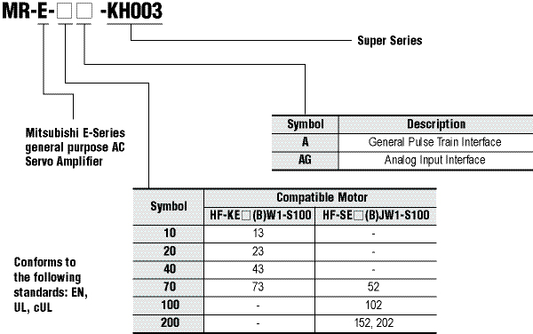
High performance and compact, the MR-E Super is an excellent choice for applications up to 2kW. The MR-E Super is available in pulse-train position or analog speed/torque models. The amplifier features Mitsubishi Electric’s legendary auto-tuning and vibration suppression functions, a 400Hz analog frequency response, and accepts pulse commands up to 500kHz. The motors are low to medium inertia up to 4500rpm and are equipped with a 131,072 pulse per revolution encoder. Set-up and diagnosis is made easy with the MR-Configurator Windows® based software.
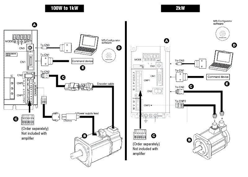
A. MR-E Super Amplifiers
B. MR-E Super Servomotors
C. Cables and Connectors
D. Software and Manuals
E. Optional Accessories
Motors
Servomotor Selection
|
Motor Series |
Rated Speed (Max. r/min) |
Rated Output Capacity (kW) |
Servomotor Brake (B) |
EN |
UL, cUL |
Protective Rating |
Features |
Application Examples | |
|
Small Capacity |
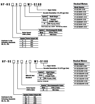
HF-KE Super Series
|
3000 (4500) |
4 Types
|
Yes |
Yes |
Yes |
IP55
|
Stable control from low speeds to high speeds allows compliance with a variety of applications. |
Belt Drive; Robots; Mounters; Sewing Machines; X-Y Tables; Food Processing Machines |
|
Medium Capacity |
HF-SE Super Series
|
2000 (3000) |
4 Types
|
Yes |
Yes |
Yes |
IP65
|
Material Handling Systems; Robots; X-Y Tables |


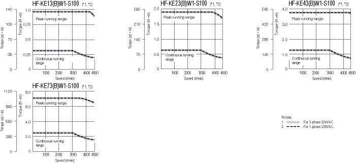
MR-E HF-KE Super 3000 r/min Series Servomotor Specifications
|
Servomotor Model |
HF-KE13W1-S100 |
HF-KE23W1-S100 |
HF-KE43W1-S100 |
HF-KE73W1-S100 | |
|
Servomotor Model with Brake |
HF-KE13BW1-S100 |
HF-KE23BW1-S100 |
HF-KE43BW1-S100 |
HF-KE73BW1-S100 | |
|
Compatible Servo Amplifier Model |
MR-E-10A-KH003 |
MR-E-20A-KH003 |
MR-E-40A-KH003 |
MR-E-70A-KH003 | |
|
Compatible Servo Amplifier with Analog Input Interface |
MR-E-10AG-KH003 |
MR-E-20AG-KH003 |
MR-E-40AG-KH003 |
MR-E-70AG-KH003 | |
|
Power Facility Capacity (kVA) (*1) |
0.3 |
0.5 |
0.9 |
1.3 | |
|
Continuous Running Duty |
Rated Output (W) |
100 |
200 |
400 |
750 |
|
Rated Torque (N·m [oz·in]) |
0.32 (45.3) |
0.64 (90.6) |
1.3 (184) |
2.4 (340) | |
|
Maximum Torque (N·m [oz·in]) |
0.95 (135) |
1.9 (269) |
3.8 (538) |
7.2 (1020) | |
|
Rated Speed (r/min) |
3000 | ||||
|
Maximum Speed (r/min) |
4500 | ||||
|
Permissible Instantaneous Speed (r/min) |
5175 | ||||
|
Power Rate At Continuous Rated Torque (kW/s) |
11.5 |
16.9 |
38.6 |
39.9 | |
|
Rated Current (A) |
0.8 |
1.4 |
2.7 |
5.2 | |
|
Maximum Current (A) |
2.4 |
4.2 |
8.1 |
15.6 | |
|
Regenerative Braking Frequency (Times/Min.) (*2, *3) |
With No Options |
(*4) |
(*4) |
249 |
140 |
|
MR-RB032 (30W) |
(*4) |
(*4) |
747 |
210 | |
|
MR-RB12 (100W) |
- |
(*4) |
2490 |
700 | |
|
MR-RB32 (300W) |
- |
- |
- |
2100 | |
|
Moment Of Inertia J (x10-4 kg • m²) [J (oz • in²)] |
Standard |
0.088 (0.481) |
0.24 (1.31) |
0.42 (2.30) |
1.43 (7.82) |
|
With Electromagnetic Brake |
0.090 (0.492) |
0.31 (1.69) |
0.50 (2.73) |
1.63 (8.91) | |
|
Recommended Load/Motor Inertia Moment Ratio |
Maximum of 15 times the servomotor’s inertia moment (*5) | ||||
|
Speed/Position Detector |
Incremental encoder (resolution per servomotor rotation: 131072 p/rev) | ||||
|
Structure |
Totally enclosed non ventilated (protection level: IP55) (*6) | ||||
|
Environment |
Ambient Temperature |
0 to 40°C (32 to 104°F) (non-freezing), storage: -15 to 70°C (5 to 158°F) (non-freezing) | |||
|
Ambient Humidity |
80% RH maximum (non-condensing), storage: 90% RH maximum (non-condensing) | ||||
|
Atmosphere |
Indoors (no direct sunlight); no corrosive gas, inflammable gas, oil mist or dust | ||||
|
Elevation/Vibration (*7) |
1000m or less above sea level; X: 49m/s² Y: 49m/s² | ||||
|
Weight kg (lb) |
Standard |
0.56 (1.3) |
0.94 (2.1) |
1.5 (3.3) |
2.9 (6.4) |
|
With Electromagnetic Brake |
0.86 (1.9) |
1.6 (3.6) |
2.1 (4.7) |
3.9 (8.6) | |
Notes:
- The power facility capacity varies depending on the power supply’s impedance.
- The regenerative braking frequency shows the permissible frequency when the motor, without a load and the optional regeneration unit, decelerates from the rated speed to a stop. When a load is connected; however, the value will be the table value/(m+1), where m=the load inertia moment/the motor inertia moment. When the operating speed exceeds the rated speed, the regenerative braking frequency is inversely proportional to the square of (operating speed/rated speed). If the operating speed changes frequently or when the regeneration is constant (as with vertical feeds), find the regenerative heating value (W) in operation. Provisions must be made to keep this heating value below the tolerable regenerative power (W). Optimal regenerative resistor varies for each system. Refer to the section “Optional Accessories • Regenerative Brake Options” in this catalog for details on the tolerable regenerative power (W).
- The regenerative braking frequency of the 600W or smaller servo amplifier may fluctuate due to the affect of the power voltage since the energy charged by the electrolytic capacitor in the servo amplifier is large.
- There are no limits on regeneration frequency as long as the effective torque is within the rated torque range. However, the load/motor of inertia moment ratio must be 15 times or less.
- Contact Mitsubishi if the load/motor of inertia moment ratio exceeds the value in the table.
- The shaft-through portion and connector for cable terminal are excluded.
- The vibration direction is shown in the right-side diagram. The numeric value indicates the maximum value of the component (commonly the bracket in the opposite direction of the motor shaft). Fretting of the bearing occurs easily when the motor stops, so maintain vibration to approximately one-half of the allowable value.

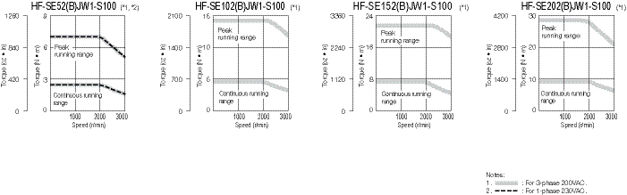
MR-E HF-SE Super 2000 r/min Series Servomotor Specifications
|
Servomotor Model |
HF-SE52JW1-S100 |
HF-SE102JW1-S100 |
HF-SE152JW1-S100 |
HF-SE202JW1-S100 | ||
|
Servomotor Model With Brake |
HF-SE52BJW1-S100 |
HF-SE102BJW1-S100 |
HF-SE152BJW1-S100 |
HF-SE202BJW1-S100 | ||
|
Compatible Servo Amplifier Model |
MR-E-70A-KH003 |
MR-E-100A-KH003 |
MR-E-200A-KH003 | |||
|
Compatible Servo Amplifier with Analog Input Interface |
MR-E-70AG-KH003 |
MR-E-100AG-KH003 |
MR-E-200AG-KH003 | |||
|
Power Facility Capacity (kVA) (*1) |
1.0 |
1.7 |
2.5 |
3.5 | ||
|
Continuous Running Duty |
Rated Output (kW) |
0.5 |
1.0 |
1.5 |
2.0 | |
|
Rated Torque (N·m [oz•in]) |
2.39 (338) |
4.77 (675) |
7.16 (1010) |
9.55 (1350) | ||
|
Maximum Torque (N•m [oz•in]) |
7.16 (1010) |
14.3 (2020) |
21.5 (3040) |
28.6 (4050) | ||
|
Rated Speed (r/min) |
2000 | |||||
|
Maximum Speed (r/min) |
3000 | |||||
|
Permissible Instantaneous Speed (r/min) |
3450 | |||||
|
Power Rate At Continuous Rated Torque (kW/s) |
9.34 |
19.2 |
28.8 |
23.8 | ||
|
Rated Current (A) |
2.9 |
5.3 |
8.0 |
10 | ||
|
Maximum Current (A) |
8.7 |
15.9 |
24 |
30 | ||
|
Regenerative Braking Frequency (Times / Min) (*2, *3) |
With No Options |
120 |
62 |
152 |
71 | |
|
MR-RB032 (30W) |
180 |
93 |
- |
- | ||
|
MR-RB12 (100W) |
600 |
310 |
- |
- | ||
|
MR-RB30 (300W) |
- |
- |
456 |
213 | ||
|
MR-RB32 (300W) |
1800 |
930 |
- |
- | ||
|
MR-RB50 (500W) |
- |
- |
760 |
355 | ||
|
Moment Of Inertia J (x10-4 kg • m²) [J (oz • in²)] |
Standard |
6.1 (33.4) |
11.9 (65.1) |
17.8 (97.3) |
38.3 (209) | |
|
With Electromagnetic Brake |
8.3 (45.4) |
14.0 (76.5) |
20.0 (109) |
47.9 (262) | ||
|
Recommended Load / Motor Inertia Moment Ratio |
Maximum of 15 times the servomotor’s inertia moment (*4) | |||||
|
Speed / Position Detector |
Incremental encoder (resolution per servomotor: 131072 p/rev) | |||||
|
Attachments |
Oil seal | |||||
|
Structure |
Totally enclosed non ventilated (protection level: IP65) (*5) | |||||
|
Environment |
Ambient Temperature |
0 to 40°C (32 to 104°F) (non-freezing), storage: -15 to 70°C (5 to 158°F) (non-freezing) | ||||
|
Ambient Humidity |
80% RH maximum (non-condensing), storage: 90% RH maximum (non-condensing) | |||||
|
Atmosphere |
Indoors (no direct sunlight); no corrosive gas, inflammable gas, oil mist or dust | |||||
|
Elevation |
1000m or less above sea level | |||||
|
Vibration (*6) |
X, Y: 24.5m/s² |
X: 24.5m/s² • Y: 49m/s² | ||||
|
Weight kg (lb) |
Standard |
4.8 (11) |
6.5 (15) |
8.3 (19) |
12 (27) | |
|
With Electromagnetic Brake |
6.7 (15) |
8.5 (19) |
11 (25) |
18 (40) | ||
Notes:
- The power facility capacity varies depending on the power supply’s impedance
- The regenerative braking frequency shows the permissible frequency when the motor, without a load and the optional regeneration unit, decelerates from the rated speed to a stop. When a load is connected; however, the value will be the table value/(m+1), where m=the load inertia moment/the motor inertia moment. When the operating speed exceeds the rated speed, the regenerative braking frequency is inversely proportional to the square of (operating speed/rated speed). If the operating speed changes frequently or when the regeneration is constant (as with vertical feeds), find the regenerative heating value (W) in operation. Provisions must be made to keep this heating value below the tolerable regenerative power (W). Optimal regenerative resistor varies for each system. Refer to the section “Optional Accessories • Regenerative Brake Options” in this catalog for details on the tolerable regenerative power (W).
- The regenerative braking frequency of the 600W or smaller servo amplifier may fluctuate due to the affect of the power voltage since the energy charged by the electrolytic capacitor in the servo amplifier is large
- Contact Mitsubishi if the load/motor of inertia moment ratio exceeds the value in the table
- The shaft-through portion is excluded.
- The vibration direction is shown in the right-side diagram. The numeric value indicates the maximum value of the component (commonly the bracket in the opposite direction of the motor shaft). Fretting of the bearing occurs easily when the motor stops, so maintain vibration to approximately one-half of the allowable value.
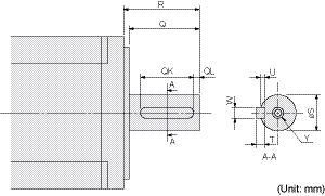
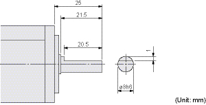
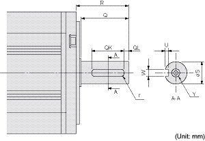
MR-E Super Shaft Detail
HF-KE_(B)W1-S100: With key (200, 400, 750W)
|
Model Number (*1) |
Variable Dimensions | ||||||||
|
T |
S |
R |
Q |
W |
QK |
QL |
U |
Y | |
|
HF-KE23(B)KW1-S100
|
5 |
14h6 |
30 |
27 |
5 |
20 |
3 |
3 |
M4 screw Depth: 15mm |
|
HF-KE73(B)KW1-S100 |
6 |
19h6 |
40 |
37 |
6 |
25 |
5 |
3.5 |
M5 screw Depth: 20mm |
HF-KE13(B)DW1-S100: D-cut (100W) (*1)
HF-SE_(B)JW1-S100: Key way - Key not included
|
Model Number (*1, *2) |
Variable Dimensions | ||||||||
|
S |
R |
Q |
W |
QK |
QL |
U |
r |
Y | |
|
HF-SE52(B)JKW1-S100
|
24h6 |
55 |
50 |
8 |
36 |
5 |
4 |
4 |
M8 screw Depth: 20mm |
|
HF-SE202(B)JKW1-S100 |
35 |
79 |
75 |
10 |
55 |
5 |
5 |
5 |
M8 screw Depth: 20mm |
Notes:
- Motors with keyway shaft (with/without key) and D-cut shaft cannot be used in frequent start/stop applications. Loose keys may damage the motor shaft.
- A key is not supplied with the motor. The key shall be installed by the user.
Optional Keys Available (Order Separately)
|
Motor Model |
Model Number |
Key Dimensions |
Stocked Item |
|
HF-SE52~152(B)JKW1-S100 |
MTR KEY 8-7-28 |
8 x 7 x 28 |
S |
|
HF-SE202(B)JKW1-S100 |
MTR KEY 10-8-45 |
10 x 8 x 45 |
S |


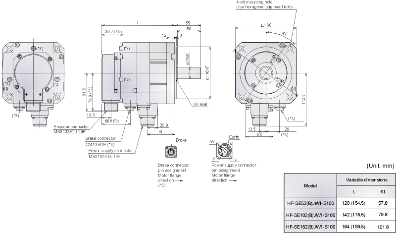
HF-KE Super Series
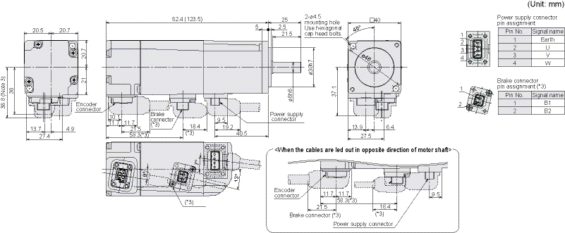
HF-KE13(B)W1-S100
HF-KE23(B)W1-S100, HF-KE43(B)W1-S100
HF-KE73(B)W1-S100
Notes:
- Use a friction coupling to fasten a load.
- Dimensions inside ( ) are for the models with an electromagnetic brake.
- Only for the models with an electromagnetic brake. The electromagnetic brake terminals (B1, B2) do not have polarity.
- For dimensions where there is no tolerance listed, use general tolerance.
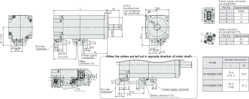
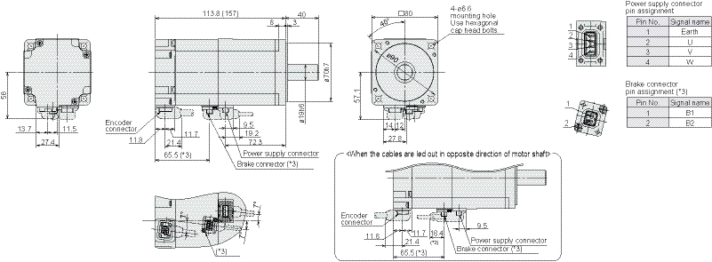
HF-SE Super Series
HF-SE52(B)JW1-S100, HF-SE102(B)JW1-S100, HF-SE152(B)JW1-S100
HF-SE202(B)JW1-S100
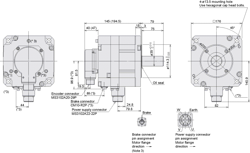
Notes:
- Use a friction coupling to fasten a load.
- Dimensions inside ( ) are for the models with an electromagnetic brake.
- Only for the models with an electromagnetic brake. The electromagnetic brake terminals do not have polarity.
- For dimensions where there is no tolerance listed, use general tolerance.
Amplifiers
Amplifier Selection
Servo Standard Specifications
|
Servo Amplifier Model |
MR-E-10A-KH003 |
MR-E-20A-KH003 |
MR-E-40A-KH003 |
MR-E-70A-KH003 |
MR-E-100A-KH003 |
MR-E-200A-KH003 | ||
|
MR-E-10AG-KH003 |
MR-E-20AG-KH003 |
MR-E-40AG-KH003 |
MR-E-70AG-KH003 |
MR-E-100AG-KH003 |
MR-E-200AG-KH003 | |||
|
Stocked Item |
S |
S |
S |
S |
S |
S | ||
|
Power Supply |
Voltage/Frequency (*1) |
3-phase 200 to 230VAC 50/60Hz or 1-phase 230VAC 50/60Hz |
3-phase 200 to 230VAC 50/60Hz | |||||
|
Permissible Voltage Fluctuation |
For 3-phase 200 to 230VAC: 3-phase 170 to 253VAC
|
3-phase 170 to 253VAC | ||||||
|
Permissible Frequency Fluctuation |
±5% maximum | |||||||
|
Control System |
Sine-wave PWM control/current control system | |||||||
|
Dynamic Brake |
Built-in | |||||||
|
Built-In Regenerative Resistor |
None |
Installed | ||||||
|
Safety Features |
Overcurrent shutdown, regeneration overvoltage shutdown, overload shutdown (electronic thermal), encoder fault protection,
| |||||||
|
A Type Amps |
Position Control Mode |
Maximum Input Pulse Frequency |
1Mpps (when using differential receiver), 200 kpps (when using open collector) | |||||
|
Positioning Feedback Pulse |
Resolution per encoder/servomotor rotation: 131072 p/rev | |||||||
|
Command Pulse Multiple |
Electronic gear A/B multiple, A: 1 to 65535, B: 1 to 65535, 1/50 < A/B < 50 | |||||||
|
Positioning Complete Width Setting |
0 to ±10000 pulses (command pulse unit) | |||||||
|
Excess Error |
±2.5 rotations | |||||||
|
Torque Limit |
Set by parameters | |||||||
|
Speed Control Mode |
Speed Control Range |
Internal speed command 1:5000 | ||||||
|
Speed Fluctuation Rate |
±0.01% maximum (load fluctuation 0 to 100%) 0% (power fluctuation ±10%) | |||||||
|
Torque Limit |
Set by parameters | |||||||
|
AG Type Amps |
Speed Control Mode |
Speed Control Range |
Analog speed command 1:2000, internal speed command 1:5000 | |||||
|
Analog Speed Command Input |
0 to ±10VDC / rated speed | |||||||
|
Speed Fluctuation Rate |
±0.01% maximum (load fluctuation 0 to 100%); 0% (power fluctuation ±10%)
| |||||||
|
Torque Limit |
Set by parameters or external analog input (0 to +10VDC/maximum torque) | |||||||
|
Torque Control Mode |
Analog Torque Command Input |
0 to ±8VDC/maximum torque (input impedance 10 to 12kΩ) | ||||||
|
Speed Limit |
Set by parameters or external analog input (0 to ±10VDC/rated speed) | |||||||
|
Structure |
Self-cooling open (IP00) |
Fan cooling open (IP00) | ||||||
|
Environment |
Ambient Temperature |
0 to 55°C (32 to 131°F) (non-freezing), storage: -20 to 65°C (-4 to 149°F) (non-freezing) | ||||||
|
Ambient Humidity |
90% RH maximum (non-condensing), storage: 90% RH maximum (non-condensing) | |||||||
|
Atmosphere |
Indoors (no direct sunlight); no corrosive gas, inflammable gas, oil mist or dust | |||||||
|
Elevation |
1000m or less above sea level | |||||||
|
Vibration |
5.9m/s² maximum | |||||||
|
Weight kg (lb) |
0.7 (1.5) |
0.7 (1.5) |
1.1 (2.4) |
1.7 (3.7) |
1.7 (3.7) |
2.0 (4.4) | ||
Note:
- Rated output and rated speed of a servomotor are applicable when the servo amplifier, combined with the servomotor, is operated within the specified power supply voltage and frequency. The torque drops when the power supply voltage is less than specified.
Cables and Connectors
HF-KE_(B)W1-S100 Series: Encoder cable length 10m or shorter
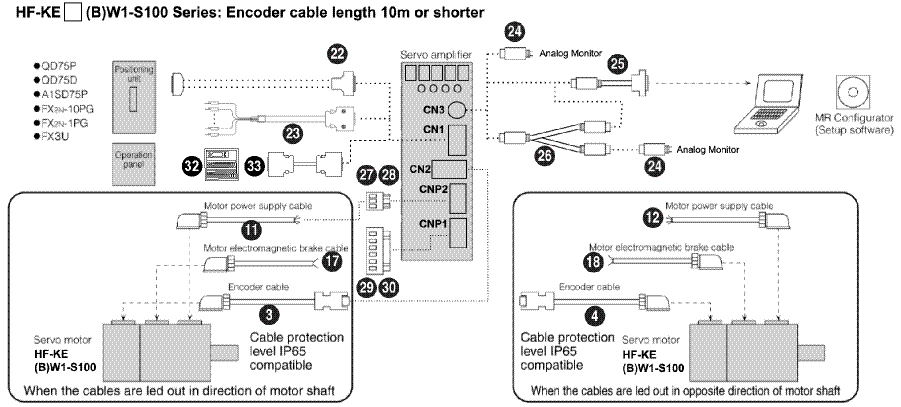
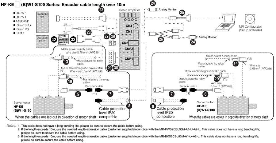
HF-KE_(B)W1-S100 Series: Encoder cable length over 10m
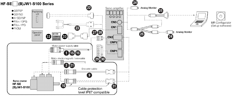
HF-SE_(B)JW1-S100 Series
MR-E Super Cables and Connectors (refer to charts above)
Power Cables for HF-SE_(B)JW1-S100
|
Item |
Model Number
|
Stocked Lengths |
Protection Level |
Diagram | ||
|
|
Standard-Flex, Unshielded Type Cables (Straight Type Connector Only) |
HF-SE52(B)JW1-S100 (*1) |
MR-J3P1-_M (*2) |
2, 5, 10, 20, 30 |
IP65 |
|
|
HF-SE102(B)JW1-S100 (*1) |
MR-J3P2-_M (*2) | |||||
|
HF-SE152(B)JW1-S100 (*1) |
MR-J3P2-_M (*2) | |||||
|
HF-SE202(B)JW1-S100 (*1) |
MR-J3P4-_M (*2) | |||||
|
High-Flex, Shielded Type Cables (Straight Type Connector Only) |
HF-SE52(B)JW1-S100 (*1) |
MR-J3PWS1-_M (*2) |
2, 5, 10, 20, 30 |
IP67 |
| |
|
HF-SE102(B)JW1-S100 (*1) |
MR-J3PWS2-_M (*2) | |||||
|
HF-SE152(B)JW1-S100 (*1) |
MR-J3PWS2-_M (*2) | |||||
|
HF-SE202(B)JW1-S100 (*1) |
MR-J3PWS4-_M (*2) | |||||


Brake Cables for HF-SE_BJW1-S100
|
Item |
Model Number
|
Stocked Lengths |
Protection Level |
Diagram | |
|
|
Standard-Flex, Unshielded Type Cables |
MR-J3BK-_M |
2, 5, 10, 20, 30 |
IP65 |
|
|
High-Flex, Shielded Type Cables |
MR-J3BRKS1-_M |
2, 5, 10, 15, 20, 30 |
IP65 |
| |


Encoder Cables for CN2 Connector for HF-KE_(B)W1-S100
|
Item |
Model Number
|
Stocked Lengths |
Protection Level |
Diagram | ||
|
|
10m or Shorter (Direct Connection Type) |
Lead Out in Direction of Motor Shaft |
MR-J3ENCBL_M-A1-H
|
2, 5, 10 |
IP65 |
|
|
MR-J3ENCBL_M-A1-L
|
2, 5, 10 |
IP65 | ||||
|
|
Lead Out in Opposite Direction of Motor Shaft |
MR-J3ENCBL_M-A2-H
|
2, 5, 10 |
IP65 | ||
|
MR-J3ENCBL_M-A2-L
|
2, 5, 10 |
IP65 | ||||
|
|
Exceeding 10m (Relay Type) |
Lead Out in Direction of Motor Shaft |
MR-J3JCBL03M-A1-L
|
S |
IP20 |
|
|
|
Lead Out in Opposite Direction of Motor Shaft |
MR-J3JCBL03M-A2-L
|
S |
IP20 | ||
|
|
Amplifier-Side Cable |
MR-EKCBL_M-H _= 20, 30, 40, or 50 (*1) |
20, 30 |
IP20 |
| |
|
MR-EKCBL_M-L _= 20 or 30 (*1) |
- |
IP20 | ||||
|
|
Junction Connector, Amplifier-Side Connector |
MR-ECNM |
S |
IP20 |
| |


Encoder Cable for CN2 Connector for HF-SE_(B)JW1-S100
|
Item |
Model Number
|
Stocked Lengths |
Protection Level |
Diagram | |
|
|
Encoder Cable |
MR-ENECBL_M-H
|
2, 5, 10 |
IP67 |
|
|
|
Encoder Connector Set |
MR-ENECNS |
S |
IP67 |
|


Motor Power Supply Cables for CNP2 for HF-KE_(B)W1-S100
|
Item |
Model Number
|
Stocked Lengths |
Protection Level |
Diagram | ||
|
|
10m or Shorter (Direct Connection Type) |
Lead Out in Direction of Motor Shaft (Non-shielded) |
MR-PWS1CBL_M-A1-H
|
2, 5, 10 |
IP65 |
|
|
MR-PWS1CBL_M-A1-L
|
2, 5, 10 |
IP65 | ||||
|
Lead Out in Direction of Motor Shaft (Shielded) |
MR-J3PS_M-A1
|
5 |
IP65 | |||
|
|
Lead Out in Opposite Direction of Motor Shaft (Non-shielded) |
MR-PWS1CBL_M-A2-H
|
2, 5, 10 |
IP65 | ||
|
MR-PWS1CBL_M-A2-L
|
2, 5, 10 |
IP65 | ||||
|
Lead Out in Opposite Direction of Motor Shaft (Shielded) |
MR-J3PS_M-A2
|
5, 10 |
IP65 | |||
|
|
Exceeding 10m (Relay Type) |
Lead Out in Direction of Motor Shaft (Non-shielded) |
MR-PWS2CBL03M-A1-L
|
S |
IP55 |
|
|
Lead Out in Direction of Motor Shaft (Shielded) |
MR-J3PS03M-A1
|
S |
IP65 | |||
|
|
Lead Out in Opposite Direction of Motor Shaft (Non-shielded) |
MR-PWS2CBL03M-A2-L
|
S |
IP55 | ||
|
Lead Out in Opposite Direction of Motor Shaft (Shielded) |
MR-J3PS03M-A2
|
S |
IP65 | |||


Notes:
- Must order separate brake cable for these motors.
- Must order separate power connector 27 or 28 to connect to the power cable.
Power Supply Connectors
|
Item |
Model Number |
Stocked Item |
Protection Level |
Diagram | |
|
|
Motors: HF-SE52(B)JW1-S100; HF-SE102(B)JW1-S100; HF-SE152(B)JW1-S100 (see |
MR-PWCNS4 (straight type only) |
S |
IP67 |
|
|
|
Motor: HF-SE202(B)JW1-S100 (see |
MR-PWCNS5 (straight type only) |
S |
IP67 |
|


Motor Brake Cables for HF-KE_BW1-S100
|
Item |
Model Number
|
Stocked Lengths |
Protection Level |
Diagram | ||
|
|
10m or Shorter (Direct Connection Type) |
Lead Out in Direction of Motor Shaft |
MR-BKS1CBL_M-A1-H _= 2, 5, or 10 (*1) |
2, 5, 10 |
IP65 |
|
|
MR-BKS1CBL_M-A1-L _= 2, 5, or 10 (*1) |
- |
IP65 | ||||
|
|
Lead Out in Opposite Direction of Motor Shaft |
MR-BKS1CBL_M-A2-H _= 2, 5, or 10 (*1) |
2, 5, 10 |
IP65 | ||
|
MR-BKS1CBL_M-A2-L _= 2, 5, or 10 (*1) |
- |
IP65 | ||||
|
|
Exceeding 10m (Relay Type) |
Lead Out in Direction of Motor Shaft |
MR-BKS2CBL03M-A1-L cable length 0.3 (*1) |
S |
IP55 |
|
|
|
Lead Out in Opposite Direction of Motor Shaft |
MR-BKS2CBL03M-A2-L cable length 0.3 (*1) |
S |
IP55 | ||


Note:
- -H and -L indicate bending life. -H indicates a long bending life and -L indicates a standard bending life.
Brake Connector Set for HF-SE_BJW1-S100
|
Item |
Model Number |
Stocked Item |
Protection Level |
Diagram | |
|
|
Brake Connector (see |
MR-BKCNS1 (straight type only) |
S |
IP67 |
|


Connector for CN1 on Amp
|
Item |
Model Number |
Stocked Item |
Protection Level |
Diagram | |
|
|
CN1 Connector (26 pin) |
MR-ECN1 |
S |
- |
|


Pigtail Cable for CN1 on Amp
|
Item |
Model Number |
Stocked Item |
Protection Level |
Diagram | |
|
|
CN1 Pigtail Cable (26 pin) |
MR-ECN1CBL-3M (3 meter cable) |
S |
- |
|


Connector and Cable Options for CN3 Connector on Amp
|
Item |
Model Number |
Stocked Lengths |
Protection Level |
Diagram | |
|
|
Analog Monitor RS-232C Connector |
MR-ECN3 |
S |
- |
|
|
|
Communication Cable |
SC-Q (3 meter cable) |
S |
- |
|
|
|
Analog Monitor RS-232C Branch Cable |
MR-E3CBL15-P |
S |
- |
|


CNP2 Power to Motor Connector
|
Item |
Model Number |
Stocked Item |
Protection Level |
Diagram | |
|
|
MR-E10 to 100A/AG-KH003 |
MR-ECNP2-B |
S |
- |
|
|
|
MR-E200A/AG-KH003 Amp Only |
MR-ECNP2-B1 |
S |
- | |


CNP1 Amp Power Input Connector
|
Item |
Model Number |
Stocked Item |
Protection Level |
Diagram | |
|
|
MR-E10 to 100A/AG-KH003 Amps |
MR-ECNP1-B |
S |
- |
|
|
|
MR-E200A/AG-KH003 Amp Only |
MR-ECNP1-B1 |
S |
- | |


CN2 Connector
|
Item |
Model Number |
Stocked Item |
Protection Level |
Diagram | |
|
|
CN2 Connector Only |
MR-J3CN2 |
S |
- |
|


For CN1
|
Item |
Model Number |
Stocked Lengths |
Protection Level |
Diagram | |
|
|
Junction Terminal Block |
MR-TB26A |
S |
- |
|
|
|
Junction Terminal Block Cable |
MR-TBNATBL_M (_ =cable length: 0.5, 1m) |
05, 1 |
- |
|


Accessories
Software and Manuals
MR-Configurator Setup Software
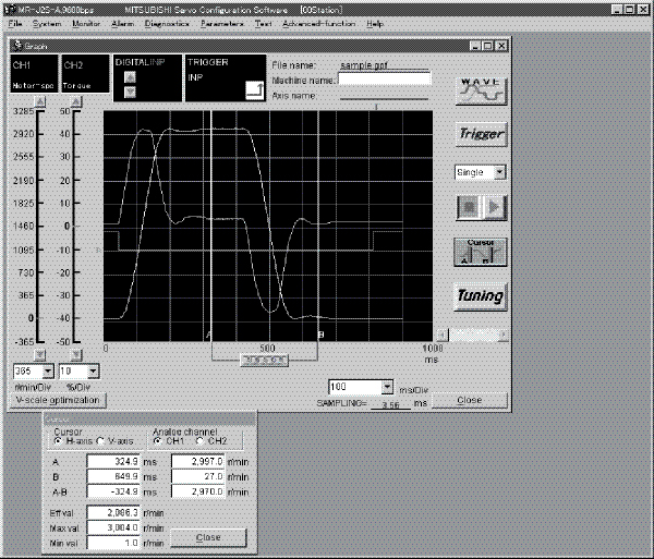
This Windows® based software package is used to setup, program and test the amplifier. Initial setup and programming is easy and quick with the user-friendly software, which has extensive help functions and drop-downs. MR-Configurator also has many diagnostic functions such as a machine simulator to aid in mechanical design, a machine analyzer to find resonant frequencies of the load and set notch filters, an alarm monitor with history data, and the ability to assign and monitor I/O.
Features:
- Can be set up using a personal computer. Works on Windows 95/98/NT/ME/2000 Professional, XP Professional*.
- Provides numerous monitor functions. Provides graph display function that enables display of servomotor status upon input signal triggers such as command pulses, droop pulses, and r/min.
- Allows servomotors to be tested easily from a personal computer.
* Windows is a registered trademark of the Microsoft Corporation.
|
Description |
Model Number |
Stocked Item |
|
Windows Communication Software |
MR-CONFIGURATOR |
S |
|
Communications Cable |
SC-Q |
S |
Manuals
|
Hardware Description |
Model Number |
Stocked Item |
|
MR-E Super |
SH(NA)030071 |
MEAU.com |
|
EMC Guidelines (Servo) Manual |
IB(NA)67310 |
MEAU.com |
Note: Many of these manuals are available for free download from our website, www.meau.com
Optional Accessories
Filters
|
Description |
Model Type |
Model Number |
Stocked Item |
|
Line Noise Filter |
All MR-E Models |
FR-BSF01 |
S |
|
Radio Noise Filter |
All MR-E Models |
FR-BIF |
S |
|
EMC Filter |
MR-E-10 to 100 |
SF1252 |
S |
|
EMC Filter |
MR-E-200 |
MF-3F480-025.230 |
- |
Regenerative Brake Options
|
Servo Amplifier |
Model Number - Regenerative Power [W] | |||||
|
Built-In Regen. Resistor |
MR-RB032 [40Ω] |
MR-RB12 [40Ω] |
MR-RB30 [40Ω] |
MR-RB32 [40Ω] |
MR-RB50 [40Ω] (Note) | |
|
Stocked Item |
N/A |
S |
S |
S |
S |
S |
|
MR-E-10 |
- |
30 |
- |
- |
- |
- |
|
MR-E-20 |
- |
30 |
100 |
- |
- |
- |
|
MR-E-40 |
10 |
30 |
100 |
- |
- | |
|
MR-E-70 |
20 |
30 |
100 |
- |
300 |
- |
|
MR-E-100 |
20 |
30 |
100 |
- |
300 |
- |
|
MR-E-200 |
100 |
- |
- |
300 |
- |
500 |
Note: Always install a cooling fan when using MR-RB50.
AC Power Improving Reactor Options
|
Model Type |
Model Number |
Stocked Item |
|
MR-E-10 to 40 |
MRL-00402 |
S |
|
MR-E-70 |
MRL-00802 |
S |
|
MR-E-100 |
MRL-01202 |
S |
|
MR-E-200 |
MRL-01802 |
S |
Информация MR-J4
Overview and Configuration
With a capacity range of 50W to 7kW (200V only), both the amplifier and motor size is reduced. We added a high resolution encoder of 4 million pulse/rev, with a speed frequency response of 2500Hz. Additional features include advanced one-touch auto tuning and advanced vibration suppression control II functions. The MR-J4 motors have the same flange size as J3 motors with the length of the motor being the same or smaller than the J3. The same cables for power, encoder and brake can be used for the MR-J3 and MR-J4. MR-J4 Series has four models: MR-J4A (analog/pulse train), MR-J4B, (SSCNET III/H), MR-J4W2B (Dual axis amplifier with SSCNET III/H) and MR-J4W3B (Three axis in one amplifier with SSCNET III/H). In addition, MR-J4 has three motor models available: HG-KR similar to HF-KP, HG-MR similar to HF-MP, and HG-SR similar to HF-SP Series. M-Size software is used to size HG Series motors and setup is made easy using MR-Configurator.
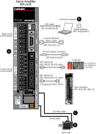
MR-J4-B
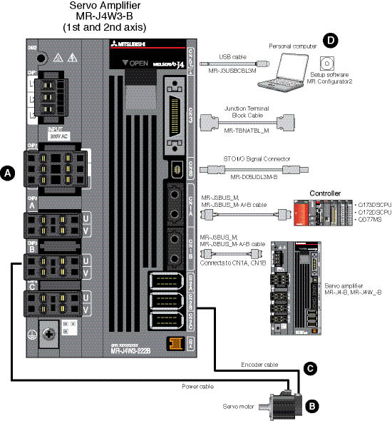
MR-J4W3-B
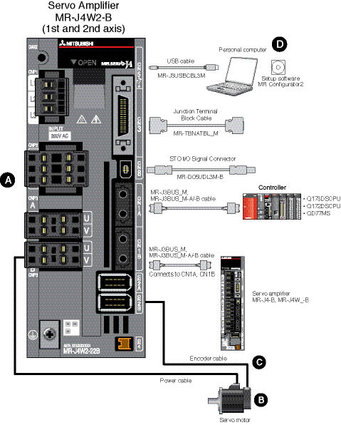
MR-J4W2-B
MR-J4-A
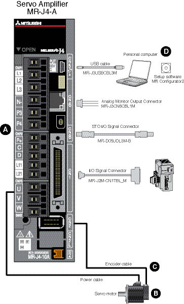
A. MR-J4 Amplifiers
B. MR-J4 Rotary Servomotors
C. Servo Amplifier Cables and Connectors
D. Software and Manuals
E. System Options
|
Rotary Servomotor Series |
Rated Speed (Max. r/min) |
Rated Output Capacity (kW) |
Servomotor Type |
Protective Degree (*2) |
Compatible Series |
Features |
Application Examples | |||
|
Electromagnetic Brake Available |
With Reducer (G1) (*1) |
With Reducer (G5, G7) (*1) | ||||||||
|
Small Capacity |
HG-KR
|
3000 (6000) |
5 Types
|
X |
X |
X |
IP65 |
HF-KP |
Low inertia: perfect for general industrial machines |
|
|
HG-MR |
3000 (6000) |
5 Types
|
X |
- |
- |
IP65 |
HF-MP |
Ultra-low inertia
Well suited for
high-throughput
operations |
| |
|
Medium Capacity |
HG-SR |
1000 (1500) |
6 Types
|
X |
- |
- |
IP67 |
HF-SP |
Medium inertia
This series is
available with two rated speeds |
|
|
2000 (3000) |
7 Types
|
X |
X |
X |
IP67 | |||||
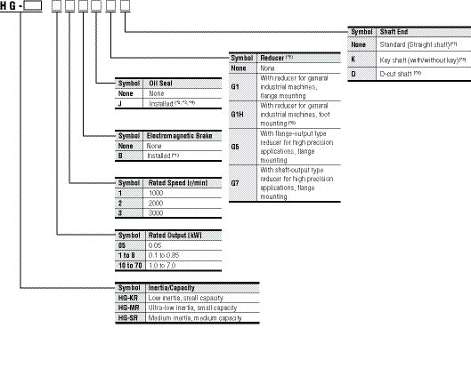
Notes:
- G1 for general industrial machines. G5 and G7 for high precision applications.
(Example Part No. = HG-KR053BG1)
Not all options available for every motor.
Notes:
- Refer to electromagnetic brake specifications of each servomotor series in this catalog for the available models and detailed specifications.
- Available in 0.1 kW or larger HG-KR/HG-MR series and all HG-SR series.
- Oil seal is not installed in the geared servomotor.
- Dimensions for HG-KR/HG-MR/HG-SR series with an oil seal are different from the standard models. Contact your local sales office for more details.
- Available only in HF-SR 2000 r/min series.
- Standard HG-SR G1/G1H has a key shaft (with key).
- Refer to special shaft end specifications of each servomotor series in this catalog for the available models and detailed specifications.
Stocked Motors
|
Model Number | |
|
HG-KR053(B) | |
|
HG-KR13(B) | |
|
HG-KR23(B) | |
|
HG-KR43(B) | |
|
HG-KR73(B) | |
|
HG-KR053(B)D | |
|
HG-KR13(B)D | |
|
HG-KR23(B)K | |
|
HG-KR43(B)K | |
|
HG-KR73(B)K | |
|
HG-MR053(B) | |
|
HG-MR13(B) | |
|
HG-MR23(B) | |
|
HG-MR43(B) | |
|
HG-MR73(B) | |
|
HG-MR053(B)D | |
|
HG-MR13(B)D | |
|
HG-MR23(B)K | |
|
HG-MR43(B)K | |
|
HG-MR73(B)K | |
|
Model Number | |
|
HG-SR52(B) | |
|
HG-SR102(B) | |
|
HG-SR152(B) | |
|
HG-SR202(B) | |
|
HG-SR352(B) | |
|
HG-SR-502(B) | |
|
HG-SR702(B) | |
|
HG-SR52(B)K | |
|
HG-SR102(B)K | |
|
HG-SR152(B)K | |
|
HG-SR202(B)K | |
|
HG-SR502(B)K | |
|
HG-SR702(B)K | |
Combinations of Rotary Servomotor and Servo Amplifier
With MR-J4 Servo Amplifier
With MR-J4 Servo Amplifier
|
Rotary Servomotor |
Servo Amplifier | ||
|
HG-KR |
HG-MR |
HG-SR | |
|
053, 13 |
053, 13 |
- |
MR-J4-10A/B |
|
23 |
23 |
- |
MR-J4-20A/B |
|
43 |
43 |
- |
MR-J4-40A/B |
|
- |
- |
51, 52 |
MR-J4-60A/B |
|
73 |
73 |
- |
MR-J4-70A/B |
|
- |
- |
81, 102 |
MR-J4-100A/B |
|
- |
- |
121, 201, 152, 202 |
MR-J4-200A/B |
|
- |
- |
301, 352 |
MR-J4-350A/B |
|
- |
- |
421, 502 |
MR-J4-500A/B |
|
- |
- |
702 |
MR-J4-700A/B |
Notes:
- Any combination of the servomotors is available such as rotary servomotor for A-axis, and linear servomotor or direct drive motor for B-axis. Refer to "Combinations of Linear Servomotor and Servo Amplifier" and "Combinations of Direct Drive Motor and Servo Amplifier" in the MR-J4 brochure.
- Any combination of the servomotors is available such as rotary servomotor for A-axis, linear servomotor for B-axis, and direct drive motor for C-axis. Refer to "Combinations of Linear Servomotor and Servo Amplifier" and "Combinations of Direct Drive Motor and Servo Amplifier" in the MR-J4 brochure.
With MR-J4W2 Servo Amplifier
|
Rotary Servomotor |
Servo Amplifier |
Axis (*1) | ||
|
HG-KR |
HG-MR |
HG-SR | ||
|
053, 13, 23 |
053, 13, 23 |
- |
MR-J4W2-22B |
A/B |
|
053, 13, 23, 43 |
053, 13, 23, 43 |
- |
MR-J4W2-44B |
A/B |
|
43, 73 |
43, 73 |
51, 52 |
MR-J4W2-77B |
A/B |
|
43, 73 |
43, 73 |
51, 81, 52, 102 |
MR-J4W2-1010B |
A/B |
With MR-J4W3 Servo Amplifier
|
Rotary Servomotor |
Servo Amplifier |
Axis (*2) | ||
|
HG-KR |
HG-MR |
HG-SR | ||
|
053, 13, 23 |
053, 13, 23 |
- |
MR-J4W3-222B |
A/B/C |
|
053, 13, 23, 43 |
053, 13, 23, 43 |
- |
MR-J4W3-444B |
A/B/C |
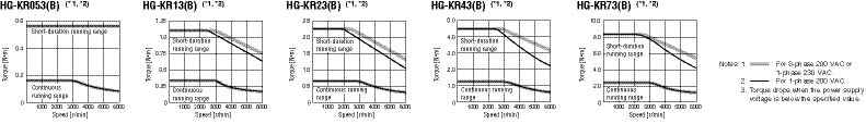
HG-KR Series (Low Inertia, Small Capacity) Specifications
|
Servomotor Model HG-KR_ |
053(B) |
13(B) |
23(B) |
43(B) |
73(B) | |
|
Servo Amplifier Model |
MR-J4-_ |
Refer to "Combinations of Servomotor and Servo Amplifier" in this guide. | ||||
|
MR-J4W_-_ | ||||||
|
Power Supply Capacity (kVA) (*1) |
0.3 |
0.3 |
0.5 |
0.9 |
1.3 | |
|
Continuous Running Duty |
Rated Output (W) |
50 |
100 |
200 |
400 |
750 |
|
Rated Torque (N•m) (*3) |
0.16 |
0.32 |
0.64 |
1.3 |
2.4 | |
|
Maximum Torque (N•m) |
0.56 |
1.1 |
2.2 |
4.5 |
8.4 | |
|
Rated Speed (r/min) |
3000 | |||||
|
Maximum Speed (r/min) |
6000 | |||||
|
Permissible Instantaneous Speed (r/min) |
6900 | |||||
|
Power Rate Continuous Rated Torque |
Standard (kW/s) |
5.63 |
13.0 |
18.3 |
43.7 |
45.2 |
|
With Electromagnetic
Brake (kW/s) |
5.37 |
12.1 |
16.7 |
41.3 |
41.6 | |
|
Rated Current (A) |
0.9 |
0.8 |
1.3 |
2.6 |
4.8 | |
|
Maximum Current (A) |
3.2 |
2.5 |
4.6 |
9.1 |
17.2 | |
|
Regenerative Braking Frequency (*2) |
MR-J4- (times/min) |
(*4) |
(*4) |
453 |
268 |
157 |
|
MR-J4W_- (times/min) |
2540 |
1370 |
451 |
268 |
393 | |
|
Moment of inertia J (x10-4kg•m²) |
Standard |
0.0450 |
0.0777 |
0.221 |
0.371 |
1.26 |
|
With Electromagnetic Brake |
0.0472 |
0.0837 |
0.243 |
0.393 |
1.37 | |
|
Recommended Load/Motor Inertia Ratio (*1) |
15 times or less |
24 times or less |
22 times or less |
15 times or less | ||
|
Speed/Position Detector |
Absolute/incremental 22-bit encoder (resolution: 4194304 pulses/rev) | |||||
|
Oil Seal |
None |
None (Servomotors with oil seal are available. (HG-KR_J)) | ||||
|
Insulation Class |
130 (B) | |||||
|
Structure |
Totally enclosed, natural cooling (IP rating: IP65) (*2) | |||||
|
Environment (*3) |
Ambient Temperature |
0°C to 40°C (non-freezing), storage: -15°C to 70°C (non-freezing) | ||||
|
Ambient Humidity |
80% RH maximum (non-condensing), storage: 90% RH maximum (non-condensing) | |||||
|
Atmosphere |
Indoors (no direct sunlight); no corrosive gas, inflammable gas, oil mist or dust | |||||
|
Elevation / Vibration (*4) |
1000 m or less above sea level; X: 49 m/s² Y: 49 m/s² | |||||
|
Vibration Rank |
V10 (*6) | |||||
|
Permissible
Load for the
Shaft (*5) |
L (mm) |
25 |
25 |
30 |
30 |
40 |
|
Radial (N) |
88 |
88 |
245 |
245 |
392 | |
|
Thrust (N) |
59 |
59 |
98 |
98 |
147 | |
|
Weight kg |
Standard |
0.34 |
0.54 |
0.91 |
1.4 |
2.8 |
|
With Electromagnetic Brake |
0.54 |
0.74 |
1.3 |
1.8 |
3.8 | |
Notes:
- Contact your local sales office if the load to motor inertia ratio exceeds the value in the table.
- The shaft-through portion is excluded. IP67 for the servomotor with oil seal. Equivalent to IP44 for the reducer portion on the geared servomotor. Refer to this guide for the shaft-through portion.
- When unbalanced torque is generated, such as in a vertical lift machine, it is recommended that the unbalanced torque of the machine be kept under 70% of the servomotor rated torque.
- When the servomotor decelerates to a stop from the rated speed, the regenerative frequency will not be limited if the effective torque is within the rated torque range.
When the servomotor decelerates to a stop from the maximum speed, the regenerative frequency will not be limited if the following requirements are met.
• HG-KR053(B): The load to motor inertia ratio is 8 times or less, and the effective torque is within the rated torque range.
• HG-KR13(B): The load to motor inertia ratio is 4 times or less, and the effective torque is within the rated torque range. - The vibration direction is shown in the diagram below. The numeric value indicates the maximum value of the component (commonly the bracket in the opposite direction of the motor shaft). Fretting of the bearing occurs easily when the motor stops, so maintain vibration to approximately one-half of the allowable value.

- Refer to the MR-J4 Servo Amplifier and Motors brochure for more detailed specifications.
HG-KR Series Electromagnetic Brake Specifications (*1)
|
Servomotor Model HG-KR_ |
053B |
13B |
23B |
43B |
73B | |
|
Type |
Spring actuated type safety brake | |||||
|
Rated Voltage |
24 VDC | |||||
|
Power Consumption (W) at 20 °C |
6.3 |
6.3 |
7.9 |
7.9 |
10 | |
|
Electromagnetic Brake Static Friction Torque (N•m) |
0.32 |
0.32 |
1.3 |
1.3 |
2.4 | |
|
Permissible Braking Work |
Per Braking (J) |
5.6 |
5.6 |
22 |
22 |
64 |
|
Per Hour (J) |
56 |
56 |
220 |
220 |
640 | |
|
Electromagnetic Brake Life (*2) |
Number of Times (Times) |
20000 | ||||
|
Work Per Braking (J) |
5.6 |
5.6 |
22 |
22 |
64 | |
Notes:
- The electromagnetic brake is for holding. It should not be used for deceleration applications.
- Brake gap is not adjustable. Electromagnetic brake life is defined as the time period until the readjustment is needed.
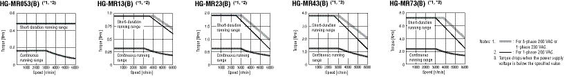
HG-MR Series (Ultra Low Inertia, Small Capacity) Specifications
|
Servomotor Model HG-MR_ |
053(B) |
13(B) |
23(B) |
43(B) |
73(B) | |
|
Servo Amplifier Model |
MR-J4-_ |
Refer to "Combinations of Servomotor and Servo Amplifier" in this guide. | ||||
|
MR-J4W_-_ | ||||||
|
Power Supply Capacity (kVA) (*1) |
0.3 |
0.3 |
0.5 |
0.9 |
1.3 | |
|
Continuous Running Duty |
Rated Output (W) |
50 |
100 |
200 |
400 |
750 |
|
Rated Torque (N•m) (*3) |
0.16 |
0.32 |
0.64 |
1.3 |
2.4 | |
|
Maximum Torque (N•m) |
0.48 |
0.95 |
1.9 |
3.8 |
7.2 | |
|
Rated Speed (r/min) |
3000 | |||||
|
Maximum Speed (r/min) |
6000 | |||||
|
Permissible Instantaneous Speed (r/min) |
6900 | |||||
|
Power Rate Continuous Rated Torque |
Standard (kW/s) |
15.6 |
33.8 |
46.9 |
114.2 |
97.3 |
|
With Electromagnetic
Brake (kW/s) |
11.3 |
28.0 |
37.2 |
98.8 |
82.1 | |
|
Rated Current (A) |
1.0 |
0.9 |
1.5 |
2.6 |
5.8 | |
|
Maximum Current (A) |
3.1 |
2.5 |
5.3 |
9.0 |
20.0 | |
|
Regenerative Braking Frequency (*2) |
MR-J4- (times/min) |
(*4) |
(*4) |
1180 |
713 |
338 |
|
MR-J4W_- (times/min) |
7540 |
3640 |
1170 |
710 |
846 | |
|
Moment of Inertia J (x10-4kg•m²) |
Standard |
0.0162 |
0.0300 |
0.0865 |
0.142 |
0.586 |
|
With Electromagnetic Brake |
0.0224 |
0.0362 |
0.109 |
0.164 |
0.694 | |
|
Recommended Load/Motor Inertia Ratio (*1) |
30 times or less | |||||
|
Speed/Position Detector |
Absolute/incremental 22-bit encoder (resolution: 4194304 pulses/rev) | |||||
|
Oil Seal |
None |
None (Servomotors with oil seal are available. (HG-MR_J)) | ||||
|
Insulation Class |
130 (B) | |||||
|
Structure |
Totally enclosed, natural cooling (IP rating: IP65) (*2) | |||||
|
Environment (*3) |
Ambient Temperature |
0°C to 40°C (non-freezing), storage: -15°C to 70°C (non-freezing) | ||||
|
Ambient Humidity |
80% RH maximum (non-condensing), storage: 90% RH maximum (non-condensing) | |||||
|
Atmosphere |
Indoors (no direct sunlight); no corrosive gas, inflammable gas, oil mist or dust | |||||
|
Elevation / Vibration (*4) |
1000 m or less above sea level; X: 49 m/s² Y: 49 m/s² | |||||
|
Vibration Rank |
V10 (*6) | |||||
|
Permissible Load for the Shaft (*5) |
L (mm) |
25 |
25 |
30 |
30 |
40 |
|
Radial (N) |
88 |
88 |
245 |
245 |
392 | |
|
Thrust (N) |
59 |
59 |
98 |
98 |
147 | |
|
Weight kg |
Standard |
0.34 |
0.54 |
0.91 |
1.4 |
2.8 |
|
With Electromagnetic Brake |
0.54 |
0.74 |
1.3 |
1.8 |
3.8 | |
Notes:
- Contact your local sales office if the load to motor inertia ratio exceeds the value in the table.
- The shaft-through portion is excluded. IP67 for the servomotor with oil seal. Refer to the asterisk 7 of "Annotations for Rotary Servomotor Specifications" on p. 2-13 in this catalog for the shaft-through portion.
- When unbalanced torque is generated, such as in a vertical lift machine, it is recommended that the unbalanced torque of the machine be kept under 70% of the servomotor rated torque.
- When the servomotor decelerates to a stop from the rated speed, the regenerative frequency will not be limited if the effective torque is within the rated torque range.
When the servomotor decelerates to a stop from the maximum speed, the regenerative frequency will not be limited if the following requirements are met.
• HG-MR053(B): The load to motor inertia ratio is 24 times or less, and the effective torque is within the rated torque range.
• HG-MR13(B): The load to motor inertia ratio is 12 times or less, and the effective torque is within the rated torque range. - The vibration direction is shown in the diagram below. The numeric value indicates the maximum value of the component (commonly the bracket in the opposite direction of the motor shaft). Fretting of the bearing occurs easily when the motor stops, so maintain vibration to approximately one-half of the allowable value.
- Refer to the MR-J4 Servo Amplifier and Motors brochure for more detailed specifications.
HG-MR Series Electromagnetic Brake Specifications (*1)
|
Servomotor Model HG-MR_ |
053B |
13B |
23B |
43B |
73B | |
|
Type |
Spring actuated type safety brake | |||||
|
Rated Voltage |
24 VDC | |||||
|
Power Consumption (W) at 20°C |
6.3 |
6.3 |
7.9 |
7.9 |
10 | |
|
Electromagnetic Brake Static Friction Torque (N•m) |
0.32 |
0.32 |
1.3 |
1.3 |
2.4 | |
|
Permissible Braking Work |
Per Braking (J) |
5.6 |
5.6 |
22 |
22 |
64 |
|
Per Hour (J) |
56 |
56 |
220 |
220 |
640 | |
|
Electromagnetic Brake Life (*2) |
Number of Times (Times) |
20000 | ||||
|
Work Per Braking (J) |
5.6 |
5.6 |
22 |
22 |
64 | |
Notes:
- The electromagnetic brake is for holding. It should not be used for deceleration applications.
- Brake gap is not adjustable. Electromagnetic brake life is defined as the time period until the readjustment is needed.
HG-SR 1000 Series (Medium Inertia, Medium Capacity) Specifications
|
Servomotor Model HG-SR_ |
51(B) |
81(B) |
121(B) |
201(B) |
301(B) |
421(B) | |
|
Servo Amplifier Model |
MR-J4-_ |
Refer to "Combinations of Servomotor and Servo Amplifier" in this guide. | |||||
|
MR-J4W_-_ | |||||||
|
Power Supply Capacity (kVA) (*1) |
1.0 |
1.5 |
2.1 |
3.5 |
4.8 |
6.3 | |
|
Continuous Running Duty |
Rated Output (kW) |
0.5 |
0.85 |
1.2 |
2.0 |
3.0 |
4.2 |
|
Rated Torque (N•m) (*3) |
4.8 |
8.1 |
11.5 |
19.1 |
28.6 |
40.1 | |
|
Maximum Torque (N•m) |
14.3 |
24.4 |
34.4 |
57.3 |
85.9 |
120 | |
|
Rated Speed (r/min) |
1000 | ||||||
|
Maximum Speed (r/min) |
1500 | ||||||
|
Permissible Instantaneous Speed (r/min) |
1725 | ||||||
|
Power Rate Continuous Rated Torque |
Standard (kW/s) |
19.7 |
41.2 |
28.1 |
46.4 |
82.3 |
107 |
|
With Electromagnetic
Brake (kW/s) |
16.5 |
36.2 |
23.2 |
41.4 |
75.3 |
99.9 | |
|
Rated Current (A) |
2.8 |
5.2 |
7.1 |
9.4 |
13 |
19 | |
|
Maximum Current (A) |
9.0 |
16.6 |
22.7 |
30.1 |
41.6 |
60.8 | |
|
Regenerative Braking Frequency (*2) |
MR-J4- (times/min) |
77 |
114 |
191 |
113 |
89 |
76 |
|
MR-J4W_- (times/min) |
392 |
286 |
- |
- |
- |
- | |
|
Moment of Inertia J (x10-4kg•m²) |
Standard |
11.6 |
16.0 |
46.8 |
78.6 |
99.7 |
151 |
|
With Electromagnetic Brake |
13.8 |
18.2 |
56.5 |
88.2 |
109 |
161 | |
|
Recommended Load/Motor Inertia Ratio (*1) |
15 times or less | ||||||
|
Speed/Position Detector |
Absolute/incremental 22-bit encoder (resolution: 4194304 pulses/rev) | ||||||
|
Oil Seal |
None (Servomotors with oil seal are available. (HG-SR_J)) | ||||||
|
Insulation Class |
155 (F) | ||||||
|
Structure |
Totally enclosed, natural cooling (IP rating: IP67) (*2) | ||||||
|
Environment (*3) |
Ambient Temperature |
0°C to 40°C (non-freezing), storage: -15°C to 70°C (non-freezing) | |||||
|
Ambient Humidity |
80% RH maximum (non-condensing), storage: 90% RH maximum (non-condensing) | ||||||
|
Atmosphere |
Indoors (no direct sunlight); no corrosive gas, inflammable gas, oil mist or dust | ||||||
|
Elevation |
1000 m or less above sea level | ||||||
|
Vibration (*4) |
X: 24.5 m/s² Y: 24.5 m/s² |
X: 24.5 m/s² Y: 49 m/s² |
X: 24.5 m/s² Y: 29.4 m/s² | ||||
|
Vibration Rank |
V10 (*5) | ||||||
|
Permissible Load for the Shaft (*5) |
L (mm) |
55 |
55 |
79 |
79 |
79 |
79 |
|
Radial (N) |
980 |
980 |
2058 |
2058 |
2058 |
2058 | |
|
Thrust (N) |
490 |
490 |
980 |
980 |
980 |
980 | |
|
Weight kg |
Standard |
6.2 |
7.3 |
11 |
16 |
20 |
27 |
|
With Electromagnetic Brake |
8.2 |
9.3 |
17 |
22 |
26 |
33 | |
Notes:
- Contact your local sales office if the load to motor inertia ratio exceeds the value in the table.
- The shaft-through portion is excluded. IP67 for the servomotor with oil seal. Refer to the Note 7 of "Annotations for Rotary Servomotor Specifications" on p. 2-13 in the MR-J4 catalog for the shaft-through portion.
- When unbalanced torque is generated, such as in a vertical lift machine, it is recommended that the unbalanced torque of the machine be kept under 70% of the servomotor rated torque.
- The vibration direction is shown in the diagram below. The numeric value indicates the maximum value of the component (commonly the bracket in the opposite direction of the motor shaft). Fretting of the bearing occurs easily when the motor stops, so maintain vibration to approximately one-half of the allowable value.
- Refer to the MR-J4 Servo Amplifier and Motors brochure for more detailed specifications.
HG-SR 1000 Series Electromagnetic Brake Specifications (*1)
|
Servomotor Model HG-SR_ |
51B |
81B |
121B |
201B |
301B |
421B | |
|
Type |
Spring actuated type safety brake | ||||||
|
Rated Voltage |
24 VDC | ||||||
|
Power Consumption (W) at 20°C |
20 |
20 |
34 |
34 |
34 |
34 | |
|
Electromagnetic Brake Static Friction Torque (N•m) |
8.5 |
8.5 |
44 |
44 |
44 |
44 | |
|
Permissible Braking Work |
Per Braking (J) |
400 |
400 |
4500 |
4500 |
4500 |
4500 |
|
Per Hour (J) |
4000 |
4000 |
45000 |
45000 |
45000 |
45000 | |
|
Electromagnetic Brake Life (*2) |
Number of Times (Times) |
20000 | |||||
|
Work Per Braking (J) |
200 |
200 |
1000 |
1000 |
1000 |
1000 | |
Notes:
- The electromagnetic brake is for holding. It should not be used for deceleration applications.
- Brake gap is not adjustable. Electromagnetic brake life is defined as the time period until the readjustment is needed.
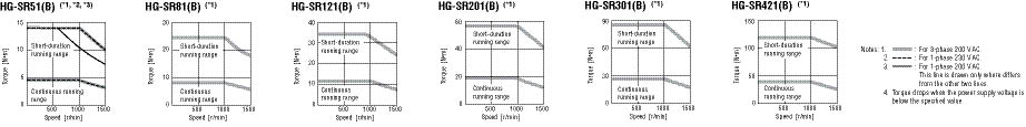
HG-SR 2000 Series (Medium Inertia, Medium Capacity) Specifications
|
Servomotor Model HG-SR_ |
52(B) |
102(B) |
152(B) |
202(B) |
352(B) |
502(B) |
702(B) | |
|
Servo Amplifier Model |
MR-J4- |
Refer to "Combinations of Servomotor and Servo Amplifier" in this guide. | ||||||
|
MR-J4W_-_ | ||||||||
|
Power Supply Capacity (kVA) (*1) |
1.0 |
1.7 |
2.5 |
3.5 |
5.5 |
7.5 |
10 | |
|
Continuous Running
|
Rated Output (kW) |
0.5 |
1.0 |
1.5 |
2.0 |
3.5 |
5.0 |
7.0 |
|
Rated Torque (N•m) (*3) |
2.4 |
4.8 |
7.2 |
9.5 |
16.7 |
23.9 |
33.4 | |
|
Maximum Torque (N•m) |
7.2 |
14.3 |
21.5 |
28.6 |
50.1 |
71.6 |
100 | |
|
Rated Speed (r/min) |
2000 | |||||||
|
Maximum Speed (r/min) |
3000 | |||||||
|
Permissible Instantaneous Speed (r/min) |
3450 | |||||||
|
Power Rate Continuous Rated Torque (kW/s) |
Standard (kW/s) |
7.85 |
19.7 |
32.1 |
19.5 |
35.5 |
57.2 |
74.0 |
|
With Electromagnetic
Brake (kW/s) |
6.01 |
16.5 |
28.2 |
16.1 |
31.7 |
52.3 |
69.4 | |
|
Rated Current (A) |
2.9 |
5.6 |
9.4 |
9.6 |
14 |
22 |
26 | |
|
Maximum Current (A) |
9.0 |
17.4 |
29.1 |
30.7 |
44.8 |
70.4 |
83.2 | |
|
Regenerative Braking Frequency (*2) |
MR-J4- (times/min) |
31 |
38 |
139 |
47 |
28 |
29 |
25 |
|
MR-J4W_- (times/min) |
154 |
96 |
- |
- |
- |
- |
- | |
|
Moment of Inertia J (x10-4kg•m²) |
Standard |
7.26 |
11.6 |
16.0 |
46.8 |
78.6 |
99.7 |
151 |
|
With Electromagnetic Brake |
9.48 |
13.8 |
18.2 |
56.5 |
88.2 |
109 |
161 | |
|
Recommended Load/Motor Inertia Ratio (*1) |
15 times or less | |||||||
|
Speed/Position Detector |
Absolute/incremental 22-bit encoder (resolution: 4194304 pulses/rev) | |||||||
|
Oil Seal |
None (Servomotors with oil seal are available. (HG-SR_J)) | |||||||
|
Insulation Class |
155 (F) | |||||||
|
Structure |
Totally enclosed, natural cooling (IP rating: IP67) (*2) | |||||||
|
Environment (*3) |
Ambient Temperature |
0°C to 40°C (non-freezing), storage: -15°C to 70°C (non-freezing) | ||||||
|
Ambient Humidity |
80% RH maximum (non-condensing), storage: 90% RH maximum (non-condensing) | |||||||
|
Atmosphere |
Indoors (no direct sunlight); no corrosive gas, inflammable gas, oil mist or dust | |||||||
|
Elevation |
1000 m or less above sea level | |||||||
|
Vibration (*4) |
X: 24.5 m/s² Y: 24.5 m/s² |
X: 24.5 m/s² Y: 49 m/s² |
X: 24.5 m/s² Y: 29.4 m/s² | |||||
|
Vibration Rank |
V10 (*5) | |||||||
|
Permissible Load for the Shaft (*5) |
L (mm) |
55 |
55 |
55 |
79 |
79 |
79 |
79 |
|
Radial (N) |
980 |
980 |
980 |
2058 |
2058 |
2058 |
2058 | |
|
Thrust (N) |
490 |
490 |
490 |
980 |
980 |
980 |
980 | |
|
Weight kg |
Standard |
4.8 |
6.2 |
7.3 |
11 |
16 |
20 |
27 |
|
With Electromagnetic Brake |
6.7 |
8.2 |
9.3 |
17 |
22 |
26 |
33 | |
Notes:
- Contact your local sales office if the load to motor inertia ratio exceeds the value in the table.
- The shaft-through portion is excluded. IP67 for the servomotor with oil seal. Refer to Note 7 of "Annotations for Rotary Servomotor Specifications" on p. 2-13 in the MR-J4 catalog for the shaft-through portion.
- When unbalanced torque is generated, such as in a vertical lift machine, it is recommended that the unbalanced torque of the machine be kept under 70% of the servomotor rated torque
- The vibration direction is shown in the diagram below. The numeric value indicates the maximum value of the component (commonly the bracket in the opposite direction of the motor shaft). Fretting of the bearing occurs easily when the motor stops, so maintain vibration to approximately one-half of the allowable value.
- Refer to the MR-J4 Servo Amplifier and Motors brochure for more detailed specifications
HG-SR 2000 Series Electromagnetic Brake Specifications (*1)
|
Servomotor Model HG-SR_ |
52B |
102B |
152B |
202B |
352B |
502B |
702B | |
|
Type |
Spring actuated type safety brake | |||||||
|
Rated Voltage |
24 VDC | |||||||
|
Power Consumption (W) at 20 °C |
20 |
20 |
20 |
34 |
34 |
34 |
34 | |
|
Electromagnetic Brake Static Friction Torque (N•m) |
8.5 |
8.5 |
8.5 |
44 |
44 |
44 |
44 | |
|
Permissible Braking Work |
Per Braking (J) |
400 |
400 |
400 |
4500 |
4500 |
4500 |
4500 |
|
Per Hour (J) |
4000 |
4000 |
4000 |
45000 |
45000 |
45000 |
45000 | |
|
Electromagnetic Brake Life (*2) |
Number of Times (Times) |
20000 | ||||||
|
Work Per Braking (J) |
200 |
200 |
200 |
1000 |
1000 |
1000 |
1000 | |
Notes:
- The electromagnetic brake is for holding. It should not be used for deceleration applications.
- Brake gap is not adjustable. Electromagnetic brake life is defined as the time period until the readjustment is needed.
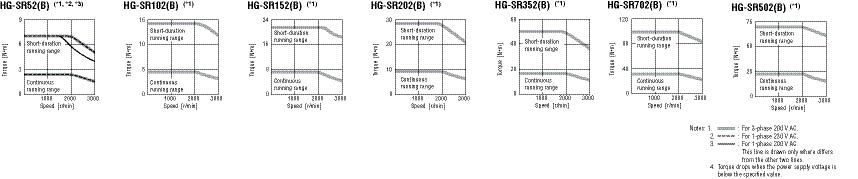
MR-J4 Motor Shaft Details and Servomotor Dimensions
HG-KR / HG-MR Series:
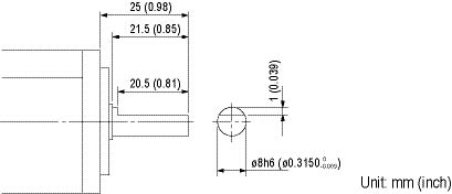
Keyway With Key Included
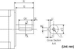
|
Motor Model |
Capacity (W) |
Variable Dimensions | ||||||||
|
T |
S |
R |
Q |
W |
QK |
QL |
U |
Y | ||
|
HG-KR_K |
23(B), 43(B) |
5
|
14h6 (0.554) |
30 (1.18) |
26 |
5
|
20 (0.79) |
3
|
3
|
M4 Depth 15 (0.59) |
|
73(B) |
6
|
19h6 (0.7480) |
40 (1.57) |
36 |
6
|
25 (0.98) |
5
|
3.5 (0.14) |
M5 Depth 20 (0.79) | |
|
Motor Model |
Capacity (W) |
Variable Dimensions | ||||||||
|
T |
S |
R |
Q |
W |
QK |
QL |
U |
Y | ||
|
HG-MR_K |
23(B), 43(B) |
5
|
14h6 (0.554) |
30 (1.18) |
26 |
5
|
20 (0.79) |
3
|
3
|
M4 Depth 15 (0.59) |
|
73(B) |
6
|
19h6 (0.7480) |
40 (1.57) |
36 |
6
|
25 (0.98) |
5
|
3.5 (0.14) |
M5 Depth 20 (0.79) | |
HG-SR Series
Keyway With No Key Supplied (Customer must supply key or order key part separately below)

|
Motor Model |
Capacity (W) |
Variable Dimensions | |||||||||||
|
S |
R |
Q |
W |
QK |
QL |
U |
r |
Y |
Key
|
Key Model Number |
Stocked
| ||
|
HG-SR_K |
51(B), 81(B) |
14h6 (0.554) |
55 |
50 |
8 |
36 |
5
|
4 |
4 |
M8 screw depth 20 |
8x7x28 |
MTR KEY 8-7-28 |
S |
|
121(B)
|
35 |
79 |
75 |
10 |
55 |
5
|
5 |
5 |
10x8x45 |
MTR KEY 10-8-45 |
S | ||
|
Motor Model |
Capacity (W) |
Variable Dimensions | |||||||||||
|
S |
R |
Q |
W |
QK |
QL |
U |
r |
Y |
Key
|
Key Model Number |
Stocked
| ||
|
HG-SR_K |
52(B), 102(B)
|
14h6 (0.554) |
55 |
50 |
8 |
36 |
5
|
4 |
4 |
M8 screw depth 20 |
8x7x28 |
MTR KEY 8-7-28 |
S |
|
202(B)
|
35 |
79 |
75 |
10 |
55 |
5
|
5 |
5 |
10x8x45 |
MTR KEY 10-8-45 |
S | ||
HG-KR/HG-MR Series Dimensions (*1, *5, *6)
HG-KR053(B), HG-KR13(B)
HG-MR053(B), HG-MR13(B)
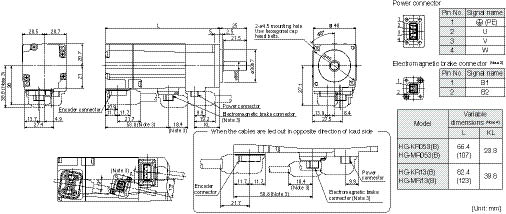
HG-KR23(B), HG-KR43(B))
HG-MR23(B), HG-MR43(B)
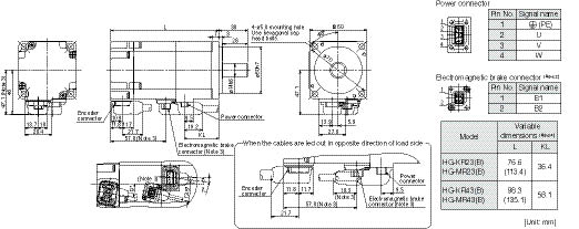
HG-KR73(B)
HG-MR73(B)
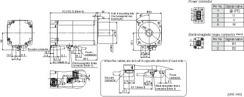
Notes:
- For dimensions without tolerance, general tolerance applies.
- The electromagnetic brake terminals (B1, B2) do not have polarity.
- Only for the models with electromagnetic brake.
- Dimensions inside ( ) are for the models with electromagnetic brake.
- Use a friction coupling to fasten a load.
- Servomotors with oil seal (HG-KR_J and HG-MR_J) have different dimensions. Contact your local sales office for more details.
HG-SR Series Dimensions (*1, *5)
HG-SR51(B), HG-SR81(B)
HG-SR52(B), HG-SR102(B), HG-SR152(B)
HG-SR51(B), HG-SR81(B)
HG-SR52(B), HG-SR102(B), HG-SR152(B)
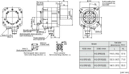
HG-SR121(B), HG-SR201(B), HG-SR301(B), HG-SR421(B)
HG-SR202(B), HG-SR352(B), HG-SR502(B), HG-SR702(B)
HG-SR202(B), HG-SR352(B), HG-SR502(B), HG-SR702(B)
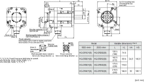
Amplifiers
X = Compatible
- = Not compatible
Amplifier Types
|
Type |
Interface |
Control Mode |
Compatible Motor Series | |||||||||||||||||
|
Pulse Train |
Analog |
SSCNET III / H |
RS-422 Multi-Drop |
Position |
Speed |
Torque |
Fully Closed Loop Control |
HG-KR |
HG-MR |
HG-SR |
LM-H3 |
LM-F |
LM-K2 |
LM-U2 |
TM-RFM | |||||
|
SSCNET III / H Interface |
MR-J4-B
|
- |
- |
X |
- |
X |
X |
X |
X |
1 axis |
3-Phase 200VAC |
0.01 ~ 7kW |
X |
X |
X |
X |
X |
X |
X |
X |
|
MR-J4W2-B |
- |
- |
X |
- |
X |
X |
X |
X |
2 axes |
3-Phase 200VAC |
0.02 ~ 1kW |
X |
X |
X |
X |
- |
X |
X |
X | |
|
MR-J4W3-B
|
- |
- |
X |
- |
X |
X |
X |
- |
3 axes |
3-Phase 200VAC |
0.02 ~ 0.04kW |
X |
X |
- |
X |
- |
X |
X |
X | |
|
General Purpose Interface |
MR-J4-A
|
X |
X |
- |
X |
X |
X |
X |
X |
1 axis |
3-Phase 200VAC |
0.01 ~ 7kW |
X |
X |
X |
X |
X |
X |
X |
X |
Note:
- The values in the table shows the rated output of the servo amplifiers. Refer to the MR-J4 brochure for the compatible servomotor.
Multi-Axis Servo Amplifier Selection
(Example Part No. = MR-J4W2-22B-ED)
1-Axis Servo Amplifier Selection
(Example Part No. = MR-J4-10B-ED)
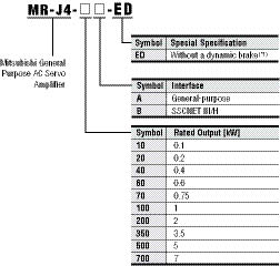
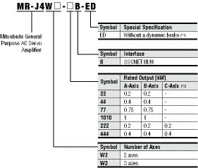
Notes:
- When using the servo amplifier without a dynamic brake, the servomotor does not stop immediately at alarm occurrence or power failure. Take measures to ensure safety on the entire system.
- For 3-axis servo amplifier.
Combinations of 1-Axis Servo Amplifier and Servomotor
|
Servo Amplifier |
Stocked Item |
Rotary Servomotor |
Linear Servomotor (Primary Side) (*1) |
Direct Drive Motor |
|
MR-J4-10B |
S |
HG-KR053, 13 HG-MR053, 13 |
- |
- |
|
MR-J4-20B |
S |
HG-KR23 HG-MR23 |
LM-U2PAB-05M-0SS0 LM-U2PBB-07M-1SS0 |
TM-RFM002C20 |
|
MR-J4-40B |
S |
HG-KR43 HG-MR43 |
LM-H3P2A-07P-BSS0 LM-H3P3A-12P-CSS0 LM-K2P1A-01M-2SS1 LM-U2PAD-10M-0SS0 LM-U2PAF-15M-0SS0 |
TM-RFM004C20 |
|
MR-J4-60B |
S |
HG-SR51, 52 |
LM-U2PBD-15M-1SS0 |
TM-RFM006C20 TM-RFM006E20 |
|
MR-J4-70B |
S |
HG-KR73 HG-MR73 |
LM-H3P3B-24P-CSS0 LM-H3P3C-36P-CSS0 LM-H3P7A-24P-ASS0 LM-K2P2A-02M-1SS1 LM-U2PBF-22M-1SS0 |
TM-RFM012E20 TM-RFM012G20 TM-RFM040J10 |
|
MR-J4-200B |
S |
HG-SR121, 201, 152, 202 |
LM-H3P3D-48P-CSS0 LM-H3P7B-48P-ASS0 LM-H3P7C-72P-ASS0 LM-FP2B-06M-1SS0 LM-K2P1C-03M-2SS1 LM-U2P2B-40M-2SS0 |
- |
|
MR-J4-350B |
S |
HG-SR301, 352 |
LM-H3P7D-96P-ASS0 LM-K2P2C-07M-1SS1 LM-K2P3C-14M-1SS1 LM-U2P2C-60M-2SS0 |
TM-RFM048G20 TM-RFM072G20 TM-RFM120J10 |
|
MR-J4-500B |
S |
HG-SR421, 502 |
LM-FP2D-12M-1SS0 LM-FP4B-12M-1SS0 LM-K2P2E-12M-1SS1 LM-K2P3E-24M-1SS1 LM-U2P2D-80M-2SS0 |
TM-RFM240J10 |
|
MR-J4-700B |
S |
HG-SR702 |
LM-FP2F-18M-1SS0 LM-FP4D-24M-1SS0 |
- |
With MR-J4-A Servo Amplifier
|
Servo Amplifier |
Stocked Item |
Rotary Servomotor |
Linear Servomotor (Primary Side) (*1) |
Direct Drive Motor |
|
MR-J4-10A |
S |
HG-KR053, 13 HG-MR053, 13 |
Available in the future |
Available in the future |
|
MR-J4-20A |
S |
HG-KR23 HG-MR23 | ||
|
MR-J4-40A |
S |
HG-KR43 HG-MR43 | ||
|
MR-J4-60A |
S |
HG-SR51, 52 | ||
|
MR-J4-70A |
S |
HG-KR73 HG-MR73 | ||
|
MR-J4-100A |
S |
HG-SR81, 102 | ||
|
MR-J4-200A |
S |
HG-SR121, 201, 152, 202 | ||
|
MR-J4-350A |
S |
HG-SR301, 352 | ||
|
MR-J4-500A |
S |
HG-SR421, 502 | ||
|
MR-J4-700A |
S |
HG-SR702 |
Note:
- Refer to “Combinations of Linear Servomotor and Servo Amplifier” under section 3 Linear Servomotor for the combinations of the primary and the secondary sides of the linear servomotors.
Combinations of Multi-Axis Servo Amplifier and Servomotor
With MR-J4W2-B Servo Amplifier
|
Servo Amplifier |
Stocked Item |
Rotary Servomotor |
Linear Servomotor (Primary Side) (*1) |
Direct Drive Motor |
|
MR-J4W2-22B |
S |
HG-KR053, 13, 23 HG-MR053, 13, 23 |
LM-U2PAB-05M-0SS0 LM-U2PBB-07M-1SS0 |
TM-RFM002C20 |
|
MR-J4W2-44B |
S |
HG-KR053, 13, 23, 43 HG-MR053, 13, 23, 43 |
LM-H3P2A-07P-BSS0 LM-H3P3A-12P-CSS0 LM-K2P1A-01M-2SS1 LM-U2PAB-05M-0SS0 LM-U2PAD-10M-0SS0 LM-U2PAF-15M-0SS0 LM-U2PBB-07M-1SS0 |
TM-RFM002C20 TM-RFM004C20 |
|
MR-J4W2-77B |
S |
HG-KR43, 73 HG-MR43, 73 HG-SR51, 52 |
LM-H3P2A-07P-BSS0 LM-H3P3A-12P-CSS0 LM-H3P3B-24P-CSS0 LM-H3P3C-36P-CSS0 LM-H3P7A-24P-ASS0 LM-K2P1A-01M-2SS1 LM-K2P2A-02M-1SS1 LM-U2PAD-10M-0SS0 LM-U2PAF-15M-0SS0 LM-U2PBD-15M-1SS0 LM-U2PBF-22M-1SS0 |
TM-RFM004C20 TM-RFM006C20 TM-RFM006E20 TM-RFM012E20 TM-RFM012G20 TM-RFM040J10 |
|
MR-J4W2-1010B |
S |
HG-KR43, 73 HG-MR43, 73 HG-SR51, 81, 52, 102 |
LM-H3P2A-07P-BSS0 LM-H3P3A-12P-CSS0 LM-H3P3B-24P-CSS0 LM-H3P3C-36P-CSS0 LM-H3P7A-24P-ASS0 LM-K2P1A-01M-2SS1 LM-K2P2A-02M-1SS1 LM-U2PAD-10M-0SS0 LM-U2PAF-15M-0SS0 LM-U2PBD-15M-1SS0 LM-U2PBF-22M-1SS0 |
TM-RFM004C20 TM-RFM006C20 TM-RFM006E20 TM-RFM012E20 TM-RFM018E20 TM-RFM012G20 TM-RFM040J10 |
With MR-J4W3-B Servo Amplifier
|
Servo Amplifier |
Stocked Item |
Rotary Servomotor |
Linear Servomotor (Primary Side) (*1) |
Direct Drive Motor |
|
MR-J4W3-222B |
S |
HG-KR053, 13, 23 HG-MR053, 13, 23 |
LM-U2PAB-05M-0SS0 LM-U2PBB-07M-1SS0 |
TM-RFM002C20 |
|
MR-J4W3-444B |
S |
HG-KR053, 13, 23, 43 HG-MR053, 13, 23, 43 |
LM-H3P2A-07P-BSS0 LM-H3P3A-12P-CSS0 LM-K2P1A-01M-2SS1 LM-U2PAB-05M-0SS0 LM-U2PAD-10M-0SS0 LM-U2PAF-15M-0SS0 LM-U2PBB-07M-1SS0 |
TM-RFM002C20 TM-RFM004C20 |
Note:
- Refer to “Combinations of Linear Servomotor and Servo Amplifier” in this guide for the combinations of the primary and the secondary sides of the linear servomotors.
MR-J4-B (SSCNET III/H Interface) Specifications
|
Servo Amplifier Model MR-J4- |
10B |
20B |
40B |
60B |
70B |
100B |
200B |
350B |
500B |
700B | |
|
Stocked Item |
S |
S |
S |
S |
S |
S |
S |
S |
S |
S | |
|
Output |
Rated Voltage |
3-phase 170 VAC | |||||||||
|
Rated Current (A) |
1.1 |
1.5 |
2.8 |
3.2 |
5.8 |
6.0 |
11.0 |
17.0 |
28.0 |
37.0 | |
|
Main Circuit Power Supply |
Voltage/Frequency (*1) |
3-phase or 1-phase 200 VAC to 240 VAC, 50/60 Hz |
3-phase 200 VAC to 240 VAC, 50/60 Hz | ||||||||
|
Rated Current (A) |
0.9 |
1.5 |
2.6 |
3.2 (*9) |
3.8 |
5.0 |
10.5 |
16.0 |
21.7 |
28.9 | |
|
Permissible Voltage Fluctuation |
3-phase or 1-phase 170 VAC to 264 VAC |
3-phase 170 VAC to 264 VAC | |||||||||
|
Permissible Frequency Fluctuation |
±5% maximum | ||||||||||
|
Control Circuit Power Supply |
Voltage/Frequency |
1-phase 200 VAC to 240 VAC, 50/60 Hz | |||||||||
|
Rated Current (A) |
0.2 |
0.3 | |||||||||
|
Permissible Voltage Fluctuation |
1-phase 170 VAC to 264 VAC | ||||||||||
|
Permissible Frequency Fluctuation |
±5% maximum | ||||||||||
|
Power Consumption (W) |
30 |
45 | |||||||||
|
Interface Power Supply |
24 VDC ±10% (required current capacity: 0.3 A (including CN8 connector signal)) | ||||||||||
|
Load-Side Encoder Interface (*8) |
Mitsubishi high-speed serial communication | ||||||||||
|
Tolerable Regenerative Power of the Built-in Regenerative Resistor (*2, *3) (W) |
- |
10 |
10 |
10 |
20 |
20 |
100 |
100 |
130 |
170 | |
|
Control Method |
Sine-wave PWM control/current control method | ||||||||||
|
Dynamic Brake |
Built-in (*4) | ||||||||||
|
Protective Functions |
Overcurrent shut-off, regenerative overvoltage shut-off, overload shut-off (electronic thermal), servomotor overheat protection, encoder error protection, regenerative error protection, undervoltage protection, instantaneous power failure protection, overspeed protection, error excessive protection, magnetic pole detection protection, linear servo control fault protection | ||||||||||
|
Fully Closed Loop Control |
Available in the future | ||||||||||
|
Safety Function (*10) |
STO (IEC/EN 61800-5-2) | ||||||||||
|
Safety Performance |
Standards Certified by CB |
EN ISO 13849-1 Category 3 PL d, EN 61508 SIL 2, EN 62061 SIL CL 2, EN 61800-5-2 SIL 2 | |||||||||
|
Response Performance |
8 ms or less (STO input OFF — energy shut-off) | ||||||||||
|
Test Pulse Input (STO) (*7) |
Test pulse frequency: 1 Hz to 25 Hz; Test pulse off time: 1 ms maximum | ||||||||||
|
Mean Time to Dangerous Failure (MTTFd) |
100 years | ||||||||||
|
Average Diagnostic Coverage (DCavg) |
90% | ||||||||||
|
Probability of Dangerous Failure Per Hour (PFH) |
1.01 × 10⁻⁷ [1/h] | ||||||||||
|
Communication Function |
USB: Connect a personal computer (MR-Configurator2 compatible) | ||||||||||
|
Compliance to Standards |
CE Marking |
LVD: EN 61800-5-1; EMC: EN 61800-3; MD: EN ISO 13849-1, EN 61800-5-2, EN 62061 | |||||||||
|
UL Standard |
UL 508C | ||||||||||
|
Structure (IP Rating) |
Natural cooling, open (IP20) |
Force cooling, open (IP20) |
Force cooling, open (IP20) (*5) | ||||||||
|
Close Mounting |
Possible (*6) |
Not possible | |||||||||
|
Weight kg |
0.8 |
0.8 |
1.0 |
1.0 |
1.4 |
1.4 |
2.1 |
2.3 |
4.0 |
6.2 | |
Notes:
- Rated output and speed of a rotary servomotor and a direct drive motor; and rated thrust and maximum speed of a linear servomotor are applicable when the servo amplifier, combined with the servomotor, is operated within the specified power supply voltage and frequency.
- Optimal regenerative option varies for each system. Select the most suitable regenerative option for your system with our capacity selection software.
- Refer to "Regenerative Option" in this catalog for the tolerable regenerative power [W] when regenerative option is used.
- When using the built-in dynamic brake, refer to "MR-J4-_B Servo Amplifier Instruction Manual" for the permissible load to motor inertia ratio and the permissible load to mass ratio.
- Terminal blocks are excluded.
- When the servo amplifiers are closely mounted, keep the ambient temperature within 0 °C to 45 °C, or use them with 75% or less of the effective load rate.
- This function makes a failure diagnosis on contacts including external circuits by instantaneously turning off the signals from a controller to a servo amplifier at constant period when the input signals of the servo amplifier are on.
- Not compatible with pulse train interface (A/B/Z-phase differential output type).
- The rated current is 2.9 A when the servo amplifier is used with UL or CSA compliant servomotor.
- Some of the models are under application. Contact your local sales office for more details.
MR-J4W2-B (2-Axis) Specifications
|
Servo Amplifier Model MR-J4W2- |
22B |
44B |
77B |
1010B | ||
|
Stocked Item |
S |
S |
S |
S | ||
|
Rated Output (kW) |
0.2 |
0.4 |
0.75 |
1 | ||
|
Output |
Rated Voltage |
3-phase 170 VAC | ||||
|
Rated Current (A) |
1.5 |
2.8 |
5.8 |
6.0 | ||
|
Main Circuit Power Supply |
Voltage/Frequency (*1) |
3-phase or 1-phase 200 VAC to 240 VAC, 50/60 Hz |
3-phase 200 VAC to 240 VAC, 50/60 Hz | |||
|
Rated Current (A) |
2.9 |
5.2 |
7.5 |
9.8 | ||
|
Permissible Voltage Fluctuation |
3-phase or 1-phase 170 VAC to 264 VAC |
3-phase 170 VAC to 264 VAC | ||||
|
Permissible Frequency Fluctuation |
±5% maximum | |||||
|
Control Circuit Power Supply |
Voltage/Frequency |
1-phase 200 VAC to 240 VAC, 50/60 Hz | ||||
|
Rated Current (A) |
0.4 | |||||
|
Permissible Voltage Fluctuation |
1-phase 170 VAC to 264 VAC | |||||
|
Permissible Frequency Fluctuation |
±5% maximum | |||||
|
Power Consumption (W) |
55 | |||||
|
Interface Power Supply |
24 VDC ±10% (required current capacity: 0.35 A (including CN8 connector signal)) | |||||
|
Load-Side Encoder Interface (*8) |
Mitsubishi high-speed serial communication | |||||
|
Capacitor Regeneration |
Reusable Regeneration Energy (J) (W) (*5) |
17 |
21 |
44 | ||
|
Moment of inertia (J) Equivalent to Permissible Charging Amount (× 10-4 kg•m²) (*6) |
3.45 |
4.26 |
8.92 | |||
|
Mass Equivalent to Permissible Charging Amount (kg) (*7) |
LM-H3 |
3.8 |
4.7 |
9.8 | ||
|
LM-K2 LM-U2 |
8.5 |
10.5 |
22.0 | |||
|
Tolerable Regenerative Power of the Built-in Regenerative Resistor (*2, *3) (W) |
20 |
100 | ||||
|
Control Method |
Sine-wave PWM control/current control method | |||||
|
Dynamic Brake |
Built-in (*4) | |||||
|
Protective Functions |
Overcurrent shut-off, regenerative overvoltage shut-off, overload shut-off (electronic thermal), servomotor overheat protection, encoder error protection, regenerative error protection, undervoltage protection, instantaneous power failure protection, overspeed protection, error excessive protection, magnetic pole detection protection, linear servo control fault protection | |||||
|
Fully Closed Loop Control |
Available in the future | |||||
|
Safety Function (*11) |
STO (IEC/EN 61800-5-2) (*10) | |||||
|
Safety Performance |
Standards Certified by CB |
EN ISO 13849-1 Category 3 PL d, EN 61508 SIL 2, EN 62061 SIL CL 2, EN 61800-5-2 SIL 2 | ||||
|
Response Performance |
8 ms or less (STO input OFF — energy shut-off) | |||||
|
Test Pulse Input (STO) (*8) |
Test pulse frequency: 1 Hz to 25 Hz; Test pulse off time: 1 ms maximum | |||||
|
Mean Time to Dangerous Failure (MTTFd) |
100 years | |||||
|
Average Diagnostic Coverage (DCavg) |
90% | |||||
|
Probability of Dangerous Failure Per Hour (PFH) |
1.01 × 10⁻⁷ [1/h] | |||||
|
Communication Function |
USB: Connect a personal computer (MR-Configurator2 compatible) | |||||
|
Compliance to Standards |
CE Marking |
LVD: EN 61800-5-1; EMC: EN 61800-3; MD: EN ISO 13849-1, EN 61800-5-2, EN 62061 | ||||
|
UL Standard |
UL 508C | |||||
|
Structure (IP Rating) |
Natural cooling, open (IP20) |
Force cooling, open (IP20) | ||||
|
Close Mounting |
Possible | |||||
|
Weight kg |
1.5 |
1.5 |
2.0 |
2.0 | ||
Notes:
- Rated output and speed of a rotary servomotor and a direct drive motor; and rated thrust and maximum speed of a linear servomotor are applicable when the servo amplifier, combined with the servomotor, is operated within the specified power supply voltage and frequency.
- Optimal regenerative option varies for each system. Select the most suitable regenerative option for your system with our capacity selection software.
- Refer to "Regenerative Option" in this catalog for the tolerable regenerative power [W] when regenerative option is used.
- When using the built-in dynamic brake, refer to "MR-J4W_-_B Servo Amplifier Instruction Manual" for the permissible load to motor inertia ratio and the permissible load to mass ratio.
- For rotary servomotors and direct drive motors, "regenerative energy" is the energy generated when a machine, which has a moment of inertia equivalent to the permissible charging amount, decelerates from the rated speed to a stop. For linear servomotors, "regenerative energy" is the energy generated when a machine, which has mass equivalent to the permissible charging amount, decelerates from the maximum speed to a stop.
- This is applicable for the rotary servomotor and the direct drive motor. When two axes are simultaneously decelerated, the permissible charging amount is equivalent to the total moments of inertia of the two axes. Otherwise, the permissible charging amount is equivalent to the moment of inertia of each axis.
- This is applicable for the linear servomotor. Mass of primary side (coil) is included. When two axes are simultaneously decelerated, the permissible charging amount is equivalent to the total masses of the two axes. Otherwise, the permissible charging amount is equivalent to the mass of each axis.
- This function makes a failure diagnosis on contacts including external circuits by instantaneously turning off the signals from a controller to a servo amplifier at constant period when the input signals of the servo amplifier are on.
- Not compatible with pulse train interface (A/B/Z-phase differential output type).
- STO is common for all axes.
- Some of the models are under application. Contact your local sales office for more details.
MR-J4W3-B (3-Axis) Specifications
|
Servo Amplifier Model MR-J4W3- |
222B |
444B | ||
|
Stocked Item |
S |
S | ||
|
Rated Output (kW) |
0.2 |
0.4 | ||
|
Output |
Rated Voltage |
3-phase 170 VAC | ||
|
Rated Current (A) |
1.5 |
2.8 | ||
|
Main Circuit Power Supply |
Voltage/Frequency (*1) |
3-phase or 1-phase 200 VAC to 240 VAC, 50/60 Hz | ||
|
Rated Current (A) |
4.3 |
7.8 | ||
|
Permissible Voltage Fluctuation |
3-phase or 1-phase 170 VAC to 264 VAC | |||
|
Permissible Frequency Fluctuation |
±5% maximum | |||
|
Control Circuit Power Supply |
Voltage/Frequency |
1-phase 200 VAC to 240 VAC, 50/60 Hz | ||
|
Rated Current (A) |
0.4 | |||
|
Permissible Voltage Fluctuation |
1-phase 170 VAC to 264 VAC | |||
|
Permissible Frequency Fluctuation |
±5% maximum | |||
|
Power Consumption (W) |
55 | |||
|
Interface Power Supply |
24 VDC ±10% (required current capacity: 0.45 A (including CN8 connector signal)) | |||
|
Capacitor Regeneration |
Reusable Regenerative Energy (J) (*5) |
21 |
30 | |
|
Moment of inertia (J) Equivalent to Permissible Charging Amount (× 10-4 kg•m²) (*6) |
4.26 |
6.08 | ||
|
Mass Equivalent to Permissible Charging Amount (kg) (*7) |
LM-H3 |
4.7 |
6.7 | |
|
LM-K2 LM-U2 |
10.5 |
15.0 | ||
|
Tolerable Regenerative Power of the Built-in Regenerative Resistor (*2, *3) (W) |
30 | |||
|
Control Method |
Sine-wave PWM control/current control method | |||
|
Dynamic Brake |
Built-in (*4) | |||
|
Protective Functions |
Overcurrent shut-off, regenerative overvoltage shut-off, overload shut-off (electronic thermal), servomotor overheat protection, encoder error protection, regenerative error protection, undervoltage protection, instantaneous power failure protection, overspeed protection, error excessive protection, magnetic pole detection protection, linear servo control fault protection | |||
|
Fully Closed Loop Control |
Not compatible | |||
|
Safety Function (*10) |
STO (IEC/EN 61800-5-2) (*9) | |||
|
Safety Performance |
Standards Certified by CB |
EN ISO 13849-1 Category 3 PL d, EN 61508 SIL 2, EN 62061 SIL CL 2, EN 61800-5-2 SIL 2 | ||
|
Response Performance |
8 ms or less (STO input OFF — energy shut-off) | |||
|
Test Pulse Input (STO) (*8) |
Test pulse frequency: 1 Hz to 25 Hz; Test pulse off time: 1 ms maximum | |||
|
Mean Time to Dangerous Failure (MTTFd) |
100 years | |||
|
Average Diagnostic Coverage (DCavg) |
90% | |||
|
Probability of Dangerous Failure Per Hour (PFH) |
1.01 × 10⁻⁷ [1/h] | |||
|
Communication Function |
USB: Connect a personal computer (MR-Configurator2 compatible) | |||
|
Compliance to Standards |
CE Marking |
LVD: EN 61800-5-1; EMC: EN 61800-3; MD: EN ISO 13849-1, EN 61800-5-2, EN 62061 | ||
|
UL Standard) |
UL 508C | |||
|
Structure (IP Rating) |
Forced cooling, open (IP20) | |||
|
Close Mounting |
Possible | |||
|
Weight kg |
1.9 |
1.9 | ||
Notes:
- Rated output and speed of a rotary servomotor and a direct drive motor; and rated thrust and maximum speed of a linear servomotor are applicable when the servo amplifier, combined with the servomotor, is operated within the specified power supply voltage and frequency.
- Optimal regenerative option varies for each system. Select the most suitable regenerative option for your system with our capacity selection software.
- Refer to "Regenerative Option" in this catalog for the tolerable regenerative power [W] when regenerative option is used.
- When using the built-in dynamic brake, refer to "MR-J4W_-_B Servo Amplifier Instruction Manual" for the permissible load to motor inertia ratio and the permissible load to mass ratio.
- For rotary servomotors and direct drive motors, "regenerative energy" is the energy generated when a machine, which has a moment of inertia equivalent to the permissible charging amount, decelerates from the rated speed to a stop. For linear servomotors, "regenerative energy" is the energy generated when a machine, which has mass equivalent to the permissible charging amount, decelerates from the maximum speed to a stop.
- This is applicable for the rotary servomotor and the direct drive motor. When three axes are simultaneously decelerated, the permissible charging amount is equivalent to the total moments of inertia of the three axes. Otherwise, the permissible charging amount is equivalent to the moment of inertia of each axis.
- This is applicable for the linear servomotor. Mass of primary side (coil) is included. When three axes are simultaneously decelerated, the permissible charging amount is equivalent to the total masses of the three axes. Otherwise, the permissible charging amount is equivalent to the mass of each axis.
- This function makes a failure diagnosis on contacts including external circuits by instantaneously turning off the signals from a controller to a servo amplifier at constant period when the input signals of the servo amplifier are on.
- STO is common for all axes.
- Some of the models are under application. Contact your local sales office for more details.
MR-J4-A (General Purpose Interface) Specifications
|
Servo Amplifier Model MR-J4- |
10A |
20A |
40A |
60A |
70A |
100A |
200A |
350A |
500A |
700A | |
|
Stocked Item |
S |
S |
S |
S |
S |
S |
S |
S |
S |
S | |
|
Output |
Rated Voltage |
3-phase 170 VAC | |||||||||
|
Rated Current (A) |
1.1 |
1.5 |
2.8 |
3.2 |
5.8 |
6.0 |
11.0 |
17.0 |
28.0 |
37.0 | |
|
Main Circuit Power Supply |
Voltage/Frequency (*1) |
3-phase or 1-phase 200 VAC to 240 VAC, 50/60 Hz |
3-phase 200 VAC to 240 VAC, 50/60 Hz | ||||||||
|
Rated Current (A) |
0.9 |
1.5 |
2.6 |
3.2 (*8) |
3.8 |
5.0 |
10.5 |
16.0 |
21.7 |
28.9 | |
|
Permissible Voltage Fluctuation |
3-phase or 1-phase 170 VAC to 264 VAC |
3-phase 170 VAC to 264 VAC | |||||||||
|
Permissible Frequency Fluctuation |
±5% maximum | ||||||||||
|
Control Circuit Power Supply |
Voltage/Frequency |
1-phase 200 VAC to 240 VAC, 50/60 Hz | |||||||||
|
Rated Current (A) |
0.2 |
0.3 | |||||||||
|
Permissible Voltage Fluctuation |
1-phase 170 VAC to 264 VAC | ||||||||||
|
Permissible Frequency Fluctuation |
±5% maximum | ||||||||||
|
Power Consumption (W) |
30 |
45 | |||||||||
|
Interface Power Supply |
24 VDC ±10% (required current capacity: 0.5 A (including CN8 connector signal)) | ||||||||||
|
Load-Side Encoder Interface (*9) |
Mitsubishi high-speed serial communication | ||||||||||
|
Tolerable Regenerative Power of the Built-in Regenerative Resistor (*2, *3) (W) |
- |
10 |
10 |
10 |
20 |
20 |
100 |
100 |
130 |
170 | |
|
Control Method |
Sine-wave PWM control/current control method | ||||||||||
|
Dynamic Brake |
Built-in (*4) | ||||||||||
|
Protective Functions |
Overcurrent shut-off, regenerative overvoltage shut-off, overload shut-off (electronic thermal), servomotor overheat protection, encoder error protection, regenerative error protection, undervoltage protection, instantaneous power failure protection, overspeed protection, error excessive protection, magnetic pole detection protection, linear servo control fault protection | ||||||||||
|
Position Control Mode |
Maximum Input Pulse Frequency |
4 Mpps (when using differential receiver), 200 kpps (when using open-collector) | |||||||||
|
Positioning Feedback Pulse |
Encoder resolution: 22 bits | ||||||||||
|
Command Pulse Multiplying Factor |
Electronic gear A/B multiple, A: 1 to 16777216, B: 1 to 16777216, 1/10 < A/B < 4000 | ||||||||||
|
Positioning Complete Width Setting |
0 pulse to ±65535 pulses (command pulse unit) | ||||||||||
|
Error Excessive |
±3 rotations | ||||||||||
|
Torque Limit |
Set by parameters or external analog input (0 VDC to +10 VDC/maximum torque) | ||||||||||
|
Speed Control Mode |
Speed Control Range |
Analog speed command 1:2000, internal speed command 1:5000 | |||||||||
|
Analog Speed Command Input |
0 VDC to ±10 VDC/rated speed (Speed at 10 V is changeable with [Pr. PC12]) | ||||||||||
|
Speed Fluctuation Rate |
±0.01% maximum (load fluctuation 0% to 100%), 0% (power fluctuation: ±10%) ±0.2% maximum (ambient temperature: 25°C ± 10°C) only when using analog speed command | ||||||||||
|
Torque Limit |
Set by parameters or external analog input (0 VDC to +10 VDC/maximum torque) | ||||||||||
|
Torque Control Mode |
Analog Torque Command Input |
0 VDC to ±8 VDC/maximum torque (input impedance: 10 kΩ to 12 kΩ) | |||||||||
|
Speed Limit |
Set by parameters or external analog input (0 VDC to ± 10 VDC/rated speed) | ||||||||||
|
Fully Closed Loop Control |
Available in the future | ||||||||||
|
Safety Function (*10) |
STO (IEC/EN 61800-5-2) | ||||||||||
|
Safety Performance |
Standards Certified by CB |
EN ISO 13849-1 Category 3 PL d, EN 61508 SIL 2, EN 62061 SIL CL 2, EN 61800-5-2 SIL 2 | |||||||||
|
Response Performance |
8 ms or less (STO input OFF — energy shut-off) | ||||||||||
|
Test Pulse Input (STO) (*7) |
Test pulse frequency: 1 Hz to 25 Hz; Test pulse off time: 1 ms maximum | ||||||||||
|
Mean Time to Dangerous Failure (MTTFd) |
100 years | ||||||||||
|
Average Diagnostic Coverage (DCavg) |
90% | ||||||||||
|
Probability of Dangerous Failure Per Hour (PFH) |
1.01 × 10⁻⁷ [1/h] | ||||||||||
|
Compliance to Standards |
CE Marking |
LVD: EN 61800-5-1; EMC: EN 61800-3; MD: EN ISO 13849-1, EN 61800-5-2, EN 62061 | |||||||||
|
UL Standard |
UL 508C | ||||||||||
|
Communication Function |
USB: Connect a personal computer (MR-Configurator2 compatible) | ||||||||||
|
RS-422: 1 : n communication (up to 32 axes) (Available in the future) | |||||||||||
|
Structure (IP Rating) |
Natural cooling, open (IP20) |
Force cooling, open (IP20) |
Force cooling, open (IP20) (*5) | ||||||||
|
Close Mounting |
Possible (*6) |
Not possible | |||||||||
|
Weight kg |
0.8 |
0.8 |
1.0 |
1.0 |
1.4 |
1.4 |
2.1 |
2.3 |
4.0 |
6.2 | |
Notes:
- Rated output and speed of a rotary servomotor are applicable when the servo amplifier, combined with the rotary servomotor, is operated within the specified power supply voltage and frequency.
- Optimal regenerative option varies for each system. Select the most suitable regenerative option for your system with our capacity selection software.
- Refer to "Regenerative Option" in this catalog for the tolerable regenerative power [W] when regenerative option is used.
- When using the built-in dynamic brake, refer to "MR-J4-_A Servo Amplifier Instruction Manual" for the permissible load to motor inertia ratio.
- Terminal blocks are excluded.
- When the servo amplifiers are closely mounted, keep the ambient temperature within 0 °C to 45 °C, or use them with 75% or less of the effective load rate.
- This function makes a failure diagnosis on contacts including external circuits by instantaneously turning off the signals from a controller to a servo amplifier at constant period when the input signals of the servo amplifier are on.
- The rated current is 2.9 A when the servo amplifier is used with UL or CSA compliant servomotor.
- Not compatible with pulse train interface (A/B/Z-phase differential output type).
- Some of the models are under application. Contact your local sales office for more details.
Cables and Connectors
MR-J4-B Type Amplifier Cables and Connectors
For 3.5 kW or smaller
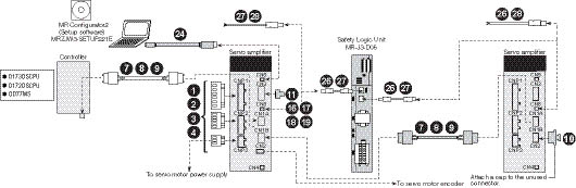
For 5 kW or larger
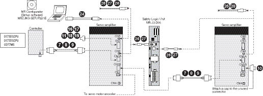
Note: Attach a SSCNET III connector cap to the unused connector.
MR-J4W2-B and MR-J4W3-B Type Amplifier Cables and Connectors
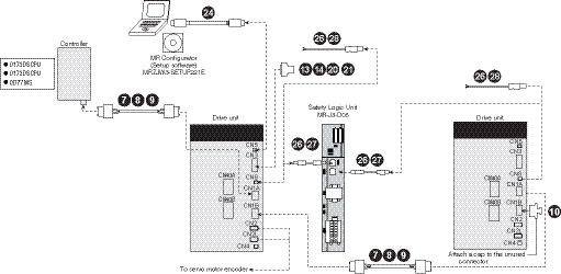
MR-J4-A Type Amplifier Cables and Connectors
For 3.5 kW or smaller
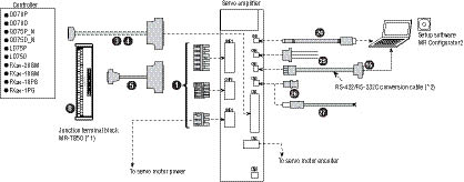
For 5 kW or larger
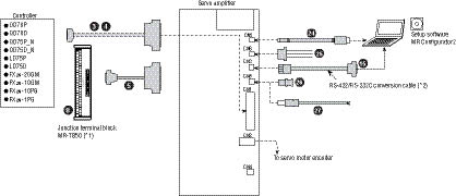
Notes:
- Refer to "Junction Terminal Block" in this selection guide.
- Refer to "Products on the Market for Servo Amplifiers" in the MR-J4 catalog.
For CNP1, CNP2, CNP3
|
Item |
Model Number |
Stocked Item |
Protection Level |
Description | |
|
|
Servo Amplifier Power Connector Set (Insertion Type) For MR-J4-100A or Smaller/MR-J4-100B or Smaller (*1, *2) |
Supplied with Amplifier |
- |
- |
|
|
Servo Amplifier Power Connector Set (Insertion Type) For MR-J4-200A/MR-J4-200B/MR-J4-350A/ MR-J4-350B (*1, *2) |
Supplied with Amplifier |
- |
- |
| |
|
|
Servo Amplifier Power Connector Set (Insertion Type) For MR-J4W2-B/MR-J4W3-B (*2, *3) |
Supplied with Amplifier |
- |
- |
|

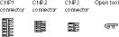

Notes:
- This connector set is not required for 5 kW or larger servo amplifiers since terminal blocks are mounted. Refer to servo amplifier dimensions in this catalog for more details.
- The wire size shows wiring specification of the connector. Refer to "Selection Example in HIV Wires for Servomotors" in this catalog for examples of wire size selection.
- Press bonding type is also available. Refer to "MR-J4W_-_B Servo Amplifier Instruction Manual" for details.
For CN1
|
Item |
Model Number |
Stocked Lengths |
Protection Level |
Description | |
|
|
Connector Set For MR-J4-A |
MR-J3CN1 |
S |
- |
|
|
|
CN1 Pigtail Cable (50 Pin) |
MR-J3CCN1CBL-_M _ = cable length 3, 5m |
3, 5 |
- |
|
|
|
Junction Terminal Block Cable
|
MR-J2M-CN1TBL_M
|
05, 1 |
- |
|
|
|
Junction Terminal Block |
MR-TB50 |
S |
- |
|
|
MR-TB50MIN (reduced size - width = 145mm (5.71 in)) |
S |
- | |||


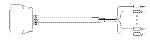


For Controller, CN1A, CN1B
|
Item |
Model Number |
Stocked Lengths |
Protection Level |
Description | |
|
|
SSCNET III Cable (Standard Cord for Inside Cabinet) Compatible With SSCNET III(/H)
|
MR-J3BUS_M _ (= cable length 0.15, 0.3, 0.5, 1, 3m) |
S |
- |
|
|
|
SSCNET III Cable (Standard Cable for Outside cabinet) Compatible With SSCNET III(/H)
|
MR-J3BUS_M-A
|
S |
- | |
|
|
SSCNET III Cable (Long Distance Cable, Long Bending Life) Compatible With SSCNET III(/H) For MR-J4-B/MR-J4W2-B/MR-J4W3-B (*1, *2) |
MR-J3BUS_M-B
|
S |
- | |
|
|
SSCNET III Connector Cap. Compatible With SSCNET III(/H). For MR-J4-B/MR-J4W2-B/MR-J4W3-B |
Supplied with Amplifier |
S |
- |
|

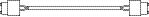


Notes:
- Read carefully through the precautions enclosed with the options before use.
- When SSCNET III/H is used, refer to "Products on the Market for Servo Amplifiers" in this catalog for cables over 50 m or with ultra-long bending life.
For CN3
|
Item |
Model Number |
Stocked Item |
Protection Level |
Description | |
|
|
Connector Set For MR-J4-B |
MR-CCN1 |
- |
- |
|
|
|
Connector Set (Qty: 1 pc) For MR-J4W2-B/
|
MR-J2CMP2 |
S |
- | |
|
|
Connector Set For MR-J4W2-B/MR-J4W3-B |
MR-ECN1 |
S |
- | |
|
|
Junction Terminal Block Cable For Connecting
|
MR-TBNATBL_M
|
S |
- |
|
|
|
RS-232 to RS-485 Converter PC to CN3 (3M) |
SC-FRPC (Cable length 3m) |
S |
- |
|
|
|
CN10 or CN3 Signal Connector (20 pin) |
MR-J2CN1 |
S |
- |
|
|
|
CN10 or CN3 Pigtail Cable (20 pin) |
MR-CCN1CBL-_M
|
3, 5 |
- |
|
|
|
Cable for PS7DW-20V14B-F Terminal Block |
MR-J2HBUS_M |
05, 1, 3, 5 |
- |
|
|
|
20 Pin Terminal B Lock for J4-B
|
PS7DW-20V14B-F |
S |
- |
|
|
|
CN6 Pigtail Cable (26 Pin) |
MR-ECN1CBL-3M |
S |
- |
|
|
|
Junction Terminal Block (Use with Cable No. 14) |
MR-TB26A |
S |
- |
|


For CN4
|
Item |
Model Number |
Stocked Lengths |
Protection Level |
Description | |
|
|
Battery Cable For Connecting MR-J4W2-B/
|
MR-BT6V1CBL_M
|
S |
- |
|
|
|
Junction Battery Cable For MR-J4W2-B/MR-J4W3-B |
MR-BT6V2CBL_M
|
S |
- |
|


For CN5 and CN6
|
Item |
Model Number |
Stocked Lengths |
Protection Level |
Description | |
|
|
CN5 Personal Computer Communication Cable (USB cable) For MR-J4-A/MR-J4-B/MR-J4W2-B/MR-J4W3-B |
MR-J3USBCBL3M |
3m |
- |
|
|
|
CN6 Monitor Cable For MR-J4-A |
MR-J3CN6CBL1M |
1m |
- |
|


For CN8
|
Item |
Model Number |
Stocked Lengths |
Protection Level |
Description | |
|
|
Short-Circuit Connector For MR-J4-A/MR-J4-B/
|
Supplied with Amplifier |
- |
- |
|
|
|
STO Cable |
MR-D05UDL-_M
|
0.3, 1, 3 |
| |
|
|
STO Cable For Connecting Servo Amplifier with MRJ3-D05 or Other Safety Control Device |
MR-D05UDL3M-B |
3m |
- |
|


For CN9 AND CN10
|
Item |
Model Number |
Stocked Lengths |
Protection Level |
Description | |
|
|
CN9 Connector |
(Standard accessory of MR-J3-D05) |
- |
- |
|
|
|
CN10 Connector |
(Standard accessory of MR-J3-D05) |
3m |
- |
|


Servomotor Cables and Connectors
For HG-KR/HG-MR Servomotor Series: Encoder Cable Length 10m or Shorter
For leading the cables out in direction of load side (*1)
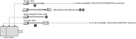
For HG-KR/HG-MR Servomotor Series: Encoder Cable Length 10m or Shorter
For leading the cables out in opposite direction of load side (*1)
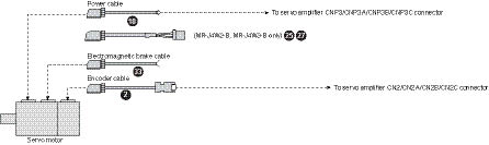
Note: Cables for leading two different directions may be used for one servomotor.
For HG-KR/HG-MR Servomotor Series: Encoder Cable Length Over 10m
For leading the cables out in direction of load side (*4)
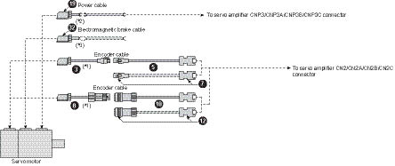
Notes:
- This cable does not have a long bending life. Thus, be sure to fix the cable before using.
- Relay a cable using MR-PWS2CBL03M-A1-L or MR-PWS2CBL03M-A2-L. This cable does not have a long bending life. Thus, be sure to fix the cable before using.
- Relay a cable using MR-BKS2CBL03M-A1-L or MR-BKS2CBL03M-A2-L. This cable does not have a long bending life. Thus, be sure to fix the cable before using.
- Cables for leading two different directions may be used for one servomotor.
- Cables drawn with dashed lines need to be fabricated by user. Refer to relevant Servomotor Instruction Manual for fabricating the cables.
For HG-KR/HG-MR Servomotor Series: Encoder Cable Length Over 10m
For leading the cables out in opposite direction of load side (*4)
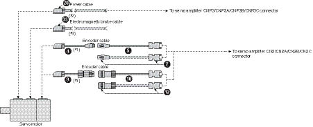
Notes:
- This cable does not have a long bending life. Thus, be sure to fix the cable before using.
- Relay a cable using MR-PWS2CBL03M-A1-L or MR-PWS2CBL03M-A2-L. This cable does not have a long bending life. Thus, be sure to fix the cable before using.
- Relay a cable using MR-BKS2CBL03M-A1-L or MR-BKS2CBL03M-A2-L. This cable does not have a long bending life. Thus, be sure to fix the cable before using.
- Cables for leading two different directions may be used for one servomotor.
- Cables drawn with dashed lines need to be fabricated by user. Refer to relevant Servomotor Instruction Manual for fabricating the cables.
For HG-SR Servomotor Series
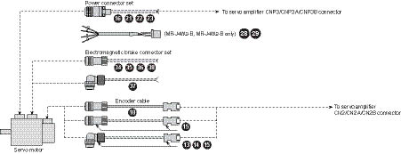
Encoder Cables and Connectors
|
Item |
Model Number
|
Stocked Lengths |
Protection Level |
Diagram | ||
|
|
Encoder Cable 10m or Shorter (Direct Connection Type) (*2) |
Lead Out in Direction of Motor Shaft For HG-KR/HG-MR |
MR-J3ENCBL_M-A1-H
|
2, 5, 10 |
IP65 |
|
|
MR-J3ENCBL_M-A1-L
|
2, 5, 10 |
IP65 | ||||
|
|
Lead Out in Opposite Direction of Motor Shaft For HG-KR/HG-MR |
MR-J3ENCBL_M-A2-H
|
2, 5, 10 |
IP65 | ||
|
MR-J3ENCBL_M-A2-L
|
2, 5, 10 |
IP65 | ||||
|
|
Encoder Cable. (Junction Type) Use This In Combination With (5) or (7). (*2) |
Lead Out in Direction of Motor Shaft For HG-KR/HG-MR |
MR-J3JCBL03M-A1-L
|
S |
IP20 |
|
|
|
Lead Out in Opposite Direction of Motor Shaft For HG-KR/HG-MR |
MR-J3JCBL03M-A2-L
|
S |
IP20 | ||
|
|
Encoder Cable. Use This In Combination With (3) or (4). |
For HG-KR/HG-MR
|
MR-EKCBL_M-H _= 20, 30, 40, or 50 (*1, *3) |
20, 30 |
IP20 |
|
|
MR-EKCBL_M-L _= 20 or 30 (*1, *3) |
- |
IP20 | ||||
|
|
For Connecting
|
Amplifier-Side Connector
|
MR-ECNM |
S |
IP20 |
|
|
|
Exceeding 10m (Relay Type)
|
For HG-KR/HG-MR (Junction Type) |
MR-J3JSCBL03M-A1-L Cable length 0.3m (*1, *3) |
S |
IP65 (*4) |
|
|
|
For HG-KR/HG-MR (Junction Type) |
MR-J3JSCBL03M-A2-L Cable length 0.3m (*1) |
S |
IP65 (*4) | ||
|
|
Encoder Cable (*2) For HG-KR/HG-MR (Junction Type) For HG-SR (Direct Connection Type)
|
MR-J3ENSCBL_M-H _ = cable length 2, 5, 10, 20, 30, 40, 50m (*1) |
2, 5, 10, 20, 30 |
IP67 |
| |
|
MR-J3ENSCBL_M-L _ = cable length 2, 5, 10, 20, 30m (*1) |
2, 5 |
IP67 | ||||
|
|
Encoder Connector Set (One-Touch Connection Type) For HG-KR/HG-MR (Junction Type) For HG-SR (Direct Connection Type) (Straight Type) |
MR-J3SCNS |
S |
IP67 |
| |
|
|
Encoder Connector Set (Screw Type) (*2, *3, *6, *7)
|
MR-ENCNS2 |
S |
IP67 | ||
|
|
Encoder Connector Set (One-Touch Connection Type)
|
MR-J3SCNSA |
S |
IP67 |
| |
|
|
Encoder Connector Set (Screw Type) (*2, *3, *6, *7) For HG-SR (Angle Type) |
MR-ENCNS2A |
S |
IP67 | ||
|
|
CN2 Connector Only |
MR-J3CN2 |
S |
- |
| |


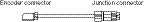
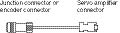


Notes:
- The IP rating indicated is for the connector's protection against ingress of dust and water when coupled to a servo amplifier/servomotor. If the IP rating of the servo amplifier/servomotor differs from that of these connectors, overall IP rating depends on the lowest of all.
- -H and -L indicate a bending life. -H indicates a long bending life, and -L indicates a standard bending life.
- This encoder cable is available in four-wire type. Parameter setting is required to use the four-wire type encoder cable. Refer to relevant Servo Amplifier Instruction Manual for more details.
- The encoder cable is rated IP65 while the junction connector itself is rated IP67.
- MR-EKCBL_M-H and MR-ECNM can be connected to an output cable for Mitutoyo Corporation scale AT343A, AT543A-SC or AT545A-SC.
- A screw thread is cut on the encoder connector of HG-SR series, and the screw type connector can be used.
- Cable clamps and bushings for cable OD of 5.5 mm to 7.5 mm and of 7.0 mm to 9.0 mm are included in the set.
Motor Power Supply Cables
|
Item |
Motor Model Number |
Cable Number ( _ = cable length 2, 5, 10, 15, 20, 25, 30 meter) |
Stocked Lengths |
Protection Level |
Description | |
|
|
Standard-Flex, Unshielded Type Cables (Straight Type Connector Only) (*2) |
HG-SR51(B), HG-SR52(B) (*1) |
MR-J3P1-_M |
2, 5, 10, 20, 30 |
IP65 |
|
|
HG-SR81(B), HG-SR102(B), HG-SR152(B) (*1) |
MR-J3P2-_M | |||||
|
HG-SR121(B), HG-SR201(B), HG-SR202(B) (*1) |
MR-J3P4-_M | |||||
|
HG-SR502(B) (*1) |
MR-J3P6-_M | |||||
|
HG-SR421(B), HG-SR702(B) (*1) |
MR-J3P7-_M | |||||
|
HG-SR301(B), HG-SR352(B) (*1) |
MR-J3P8-_M | |||||
|
High-Flex, Shielded Type Cables (Straight Type Connector Only) (*2) |
HG-SR51(B), HG-SR52(B), HG-SR152(B) (*1) |
MR-J3PWS1-_M |
2, 5 10, 15, 20, 30 |
IP67 |
| |
|
HG-SR81(B), HG-SR102(B) (*1) |
MR-J3PWS2-_M | |||||
|
HG-SR121(B), HG-SR201(B), HG-SR202(B) (*1) |
MR-J3PWS4-_M | |||||
|
HG-SR502(B) (*1) |
MR-J3PWS6-_M | |||||
|
HG-SR421(B), HG-SR702(B) (*1) |
MR-J3PWS7-_M | |||||
|
HG-SR301(B), HG-SR352(B) (*1) |
MR-J3PWS9-_M | |||||
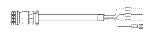
Notes:
- Must order separate brake cable for these motors.
Motor Power Supply Cables
|
Item |
Model Number |
Stocked Lengths |
Protection Level (*1) |
Description | ||
|
|
10m Or Shorter (Direct Connection Type |
Power Supply Cable For HG-KR/ HG-MR. Lead Out In Direction Of Motor Shaft (Non-Shielded) (*2) |
MR-PWS1CBL_M-A1-H (_ = cable length 2, 5, 10m) (*1) |
2, 5, 10 |
IP65 |
|
|
MR-PWS1CBL_M-A1-L (_ = cable length 2, 5, 10m) (*1) |
2, 5, 10 |
IP65 | ||||
|
|
Power Supply Cable For HG-KR/ HG-MR. Lead Out In Opposite Direction of Motor Shaft (Non-Shielded) (*2) |
MR-PWS1CBL_M-A2-H (_ = cable length 2, 5, 10m) (*1) |
2, 5, 10 |
IP65 | ||
|
MR-PWS1CBL_M-A2-L (_ = cable length 2, 5, 10m) (*1) |
2, 5, 10 |
IP65 | ||||
|
|
Exceeding 10m (Relay Type) |
Power Supply Cable For HG-KR/HG-MR (Junction Type) Motor Lead Out In Direction Of Motor Shaft (Non-Shielded) (*2) |
MR-PWS2CBL03M-A1-L
|
S |
IP55 |
|
|
|
Power Supply Cable For HG-KR/HG-MR (Junction Type) Motor Lead Out In Opposite Direction Of Motor Shaft (Non-Shielded) (*2) |
MR-PWS2CBL03M-A2-L
|
S |
IP55 | ||
|
|
Power Connector Set For HG-SR51, 81, 52, 102, 152 |
MR-PWCNS4 (*2) |
- |
IP67 |
| |
|
|
Power Connector Set For HG-SR121, 201, 301, 202, 352, 502 |
MR-PWCNS5 (*2) |
- |
IP67 | ||
|
|
Power Connector Set For HG-SR421, 702 |
MR-PWCNS3 (*2) |
- |
IP67 | ||


Notes:
- The IP rating indicated is for the connector's protection against ingress of dust and water when coupled to a servo amplifier/servomotor. If the IP rating of the servo amplifier/servomotor differs from that of these connectors, overall IP rating depends on the lowest of all.
2. -H and -L indicate a bending life. -H indicates a long bending life, and -L indicates a standard bending life.
Power Supply Cable for HF-KP/HF-MP Rotary Servomotors (Direct Connection Type)
|
Item |
Model |
Stocked Lengths |
Protection Level |
Description | |
|
|
Lead Out in Direction of Motor Shaft Standard Bending Life |
SC-EPWS1CBL_M-A1-L (_= cable length: 2, 5, 10m) |
- |
- |
|
|
|
Lead Out in Opposite Direction of Motor Shaft Standard Bending Life |
SC-EPWS1CBL_M-A2-L (_= cable length: 2, 5, 10m) |
- |
- | |
|
|
Lead Out in Direction of Motor Shaft Long Bending Life |
SC-EPWS1CBL_M-A1-H (_= cable length: 2, 5, 10m) |
2, 5, 10 |
- | |
|
|
Lead out in Opposite Direction of Motor Shaft Long Bending Life |
SC-EPWS1CBL_M-A2-H (_= cable length: 2, 5, 10m) |
2, 5, 10 |
- | |
Power Supply Cable for MR-J4W2 and MR-J4W3
|
Item |
Model |
Stocked Lengths |
Protection Level |
Description | |
|
|
Standard Bending Life |
SC-EPWS2CBL_M-L (_= cable length: 2, 5, 10, 20, 30m) |
- |
- |
|
|
|
Long Bending Life |
SC-EPWS2CBL_M-H (_= cable length: 2, 5, 10, 20, 30m) |
2, 5, 10 |
- | |

Motor Brake Cables for HG-KR/HG-MR Rotary Servomotors
|
Item |
Model Number
|
Stocked Lengths |
Protection Level (*1) |
Diagram | ||
|
|
Brake Cable for
|
Lead Out in Direction of Motor Shaft |
MR-BKS1CBL_M-A1-H (_= 2, 5, or 10) (*1) |
2, 5, 10 |
IP65 |
|
|
MR-BKS1CBL_M-A1-L (_= 2, 5, or 10) (*1) |
- |
IP65 | ||||
|
|
Lead Out in Opposite Direction of Motor Shaft |
MR-BKS1CBL_M-A2-H (_= 2, 5, or 10) (*1) |
2, 5, 10 |
IP65 | ||
|
MR-BKS1CBL_M-A2-L _= 2, 5, or 10 (*1) |
- |
IP65 | ||||
|
|
Brake Cable for
|
Lead Out in Direction of Motor Shaft |
MR-BKS2CBL03M-A1-L (cable length 0.3) (*1) |
S |
IP55 |
|
|
|
Lead Out in Opposite Direction of Motor Shaft |
MR-BKS2CBL03M-A2-L (cable length 0.3) (*1) |
S |
IP55 | ||
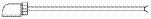


Notes:
- The IP rating indicated is for the connector's protection against ingress of dust and water when coupled to a servo amplifier/servomotor. If the IP rating of the servo amplifier/servomotor differs from that of these connectors, overall IP rating depends on the lowest of all.
- -H and -L indicate a bending life. -H indicates a long bending life, and -L indicates a standard bending life.
Brake Cables for HG-SR Servomotor Series
|
Item |
Model Number
|
Stocked Lengths |
Protection Level |
Diagram | |
|
|
Standard-Flex, Unshielded Type Cables |
MR-J3BK-_M |
2, 5, 10, 20, 30 |
IP65 |
|
|
High-Flex, Shielded Type Cables |
MR-J3BRKS1-_M |
2, 5, 10, 15, 20, 30 |
IP65 |
| |

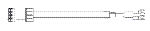
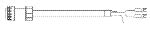
Brake Connector Set
|
Item |
Model Number |
Stocked Lengths |
Protection Level (*1) |
Diagram | |
|
|
Electromagnetic Brake Connector Set (One-Touch Connection Type) For HG-SR (Straight Type) |
MR-BKCNS1 |
S |
IP67 |
|
|
|
Electromagnetic Brake Connector Set (Screw Type) For HG-SR (Straight Type) (*2) |
MR-BKCNS2 |
S |
IP67 | |
|
|
Electromagnetic Brake Connector Set (One-Touch Connection Type) For HG-SR (Angle Type) |
MR-BKCNS1A |
S |
IP67 |
|
|
|
Electromagnetic Brake Connector Set (Screw type) For HG-SR (Angle Type) (*2) |
MR-BKCNS1A |
S |
IP67 |
|


Notes:
- The IP rating indicated is for the connector's protection against ingress of dust and water when coupled to a servo amplifier/servomotor. If the IP rating of the servo amplifier/servomotor differs from that of these connectors, overall IP rating depends on the lowest of all.
- A screw thread is cut on the electromagnetic brake connector of HG-SR Series and the screw type connector can be used.
Accessories
Software and Manuals
Servo Support Software • (MRZJW3-MOTSZ111E)
This software makes it easy to perform setup, tuning, monitor display, diagnostics, reading and writing of parameters, and test operations with a personal computer. User-satisfying functions that enable the balance with the machine system, optimum control and short start up time are available.
- This software can set up and tune your servo system easily with a personal computer.
- Multiple monitor functions. Graphic display functions are provided to display the servomotor status with the input signal triggers, such as the command pulse, droop pulse and speed.
- Test operations with a personal computer. Test operation of the servomotors can be performed with a personal computer using multiple test mode menus.
- Further advanced tuning is possible with the improved advanced functions.
|
Hardware Description |
Model Number |
Stocked Item |
|
MR-J4B Instruction Manual |
SH(NA)030106-A |
MEAU.com |
|
MR-J4A Instruction Manual |
SH(NA)030107-A |
MEAU.com |
|
MR-J4W Instruction Manual |
SH(NA)030105-A |
MEAU.com |
|
Description |
Model Number |
Stocked Item |
|
Windows Communication Software |
MR-CONFIGURATOR2 |
S |
|
Communication Cable |
MR-J3USBCBL3M |
S |
System Options
Line Noise Filter
|
Servo Amplifier Type |
Model Number |
Stocked Item |
Description |
|
MR-J4_
|
FR-BSF01 |
S |
|
|
MR-J4_
|
FR-BLF |
S |

Radio Noise Filter
|
Servo Amplifier Type |
Model Number |
Stocked Item |
Description |
|
All J4 Models |
FR-BIF |
S |
|

Manual Pulse Generator
|
Servo Amplifier Type |
Model Number |
Stocked Item |
Description |
|
MR-J4-A Only |
MR-HDP01 |
S |
|

EMC Filter (*1)
|
Servo Amplifier Type |
Model Number |
Stocked Item |
Description |
|
MR-J4-10A/B to 100A/B MR-J4W2-22B MR-J4W3-222B |
HF3010A-UN (*1) |
- |
|
|
MR-J4W2-44B |
HF3010A-UN2 (*1) |
- | |
|
MR-J4-200A/B, 350A/B MR-J4W2-77B, 1010B MR-J4W3-444B |
HF3030A-UN (*1) |
- | |
|
MR-J4-500A/B, 700A/B |
HF3040A-UN (*1) |
- |

Note: Contact MEAU for additional filter opportunities.
- Manufactured by Soshin Electric Co., Ltd. A surge protector is separately required to use this EMC filter. Refer to "EMC Installation Guidelines."
20 Pin Terminal Block (*1)
|
Servo Amplifier Type |
Model Number |
Stocked Item |
Description |
|
MR-J3-B Safety Only |
PS7DW-20V14B-F |
S |
|

Note: MR-TB20 terminal block cannot be used for MR-J3-B Safety.
Battery
|
Item Number |
Model Number |
Description |
Stocked Item |
Description |
|
Battery |
MR-BAT6V1SET |
The servomotor’s absolute value can be maintained by installing the battery in the servo amplifier. The battery is not required when the servo system is used in an incremental mode. |
S |
|
|
Battery |
MR-BAT6V1 |
The battery case and the batteries are required when configuring absolute position detection system using the rotary servomotor or the direct drive motor. MR-BT6VCASE is a case that stores 5 pieces of MR-BAT6V1 batteries by connecting the connectors. Up to 8 axes of MR-J4W_-_B servo amplifiers are able to be connected to this battery case. Use optional MR-BT6V2CBL_M junction battery cable for branching off the connection when connecting multiple servo amplifiers. MR-BT6VCASE and MR-BAT6V1 are not required when using the linear servomotor or when configuring incremental system with the MR-J4W_-B servo amplifier. MR-BAT6V1 is not included with MR-BT6VCASE. Please purchase the batteries separately. |
S |
|
|
Battery Case |
MR-BT6VCASE |
S |
|
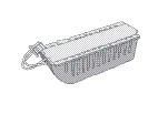
Power Factor Improving DC Reactor
|
Servo Amplifier Type |
Model Number |
Stocked Item |
Description |
|
MR-J4-10A/B, MR-J4-20A/B |
FR-HEL-0.4K |
- |
|
|
MR-J4-40A/B |
FR-HEL-0.75K |
- | |
|
MR-J4-60A/B, MR-J4-70A/B |
FR-HEL-1.5K |
- | |
|
MR-J4-100A/B |
FR-HEL-2.2K |
- | |
|
MR-J4-200A/B |
FR-HEL-3.7K |
- | |
|
MR-J4-350A/B |
FR-HEL-7.5K |
- | |
|
MR-J4-500A/B |
FR-HEL-11K |
- | |
|
MR-J4-700A/B |
FR-HEL-15K |
- |

Power Factor Improving AC Reactor
|
Servo Amplifier Type |
Model Number |
Stocked Item |
Description |
|
MR-J4-10A/B, MR-J4-20A/B |
FR-HAL-0.4K |
- |
|
|
MR-J4-40A/B |
FR-HAL-0.75K |
- | |
|
MR-J4-60A/B, MR-J4-70A/B |
FR-HAL-1.5K |
- | |
|
MR-J4-100A/B |
FR-HAL-2.2K |
- | |
|
MR-J4-200A/B |
FR-HAL-3.7K |
- | |
|
MR-J4-350A/B |
FR-HAL-7.5K |
- | |
|
MR-J4-500A/B |
FR-HAL-11K |
- | |
|
MR-J4-700A/B |
FR-HAL-15K |
- |

Optional Regeneration Resistors
|
Servo Amplifier Model MR-J4-_ |
Built-in Regenerative Resistor/Tolerable Regenerative Power (W) |
Optional Regeneration Resistors/Tolerable Regenerative Power (W) (*2) | ||||||||||
|
MR-RB | ||||||||||||
|
032 (40Ω) |
12 (40Ω) |
30 (13Ω) |
3N (9Ω) |
31 (6.7Ω) |
32 (40Ω) |
50 (13Ω)(*1) |
5N (9Ω)(*1) |
51 (6.7Ω)(*1) |
14 (26Ω) |
34 (26Ω) | ||
|
Stocked Item |
- |
S |
S |
S |
S |
S |
S |
S |
S |
S |
- |
- |
|
MR-J4-10A/B |
- |
30 |
- |
- |
- |
- |
- |
- |
- |
- |
- |
- |
|
MR-J4-20A/B |
10 |
30 |
100 |
- |
- |
- |
- |
- |
- |
- |
- |
- |
|
MR-J4-40A/B |
10 |
30 |
100 |
- |
- |
- |
- |
- |
- |
- |
- |
- |
|
MR-J4-60A/B |
10 |
30 |
100 |
- |
- |
- |
- |
- |
- |
- |
- |
- |
|
MR-J4-70A/B |
20 |
30 |
100 |
- |
- |
- |
300 |
- |
- |
- |
- |
- |
|
MR-J4-100A/B |
20 |
30 |
100 |
- |
- |
- |
300 |
- |
- |
- |
- |
- |
|
MR-J4-200A/B |
100 |
- |
- |
300 |
- |
- |
- |
500 |
- |
- |
- |
- |
|
MR-J4-350A/B |
100 |
- |
- |
- |
300 |
- |
- |
- |
500 |
- |
- |
- |
|
MR-J4-500A/B |
130 |
- |
- |
- |
- |
300 |
- |
- |
- |
500 |
- |
- |
|
MR-J4-700A/B |
170 |
- |
- |
- |
- |
300 |
- |
- |
- |
500 |
- |
- |
|
MR-J4W2-22B |
20 |
- |
- |
- |
- |
- |
- |
- |
- |
- |
100 |
- |
|
MR-J4W2-44B |
20 |
- |
- |
- |
- |
- |
- |
- |
- |
- |
100 |
- |
|
MR-J4W2-77B |
100 |
- |
- |
- |
300 |
- |
- |
- |
- |
- |
- |
- |
|
MR-J4W2-1010B |
100 |
- |
- |
- |
300 |
- |
- |
- |
- |
- |
- |
- |
|
MR-J4W3-222B |
30 |
- |
- |
- |
- |
- |
- |
- |
- |
- |
100 |
300 |
|
MR-J4W3-444B |
30 |
- |
- |
- |
- |
- |
- |
- |
- |
- |
100 |
300 |
Notes:
- Be sure to cool the unit forcibly with a cooling fan (92 mm × 92 mm, minimum air flow: 1.0 m³/min). The cooling fan must be prepared by user.
- The power values in this table are resistor-generated powers, not rated powers
Информация MR-J3
Overview and Configuration
With a capacity range of 50W to 55kW, we reduced the size of both the amplifier and motor, added a high resolution encoder and advanced auto-tuning and vibration control. The J3’s high torque motor can operate at up to 6000 rpm, and with a speed frequency response of 2100Hz. Twenty percent smaller than its predecessor, the J3’s high resolution 262,144ppr encoder is mounted as standard to provide stability even at low speeds. Mitsubishi Electric Automation’s original model adaptive control and ever-evolving automatic tuning function makes precise tuning easy and the J3’s advanced vibration control suppresses vibrations automatically. Set-up, diagnostics, and tuning are easy, thanks to MR-Configurator, a Windows™ -based software package. MR-Configurator has many improved diagnostic functions, such as an advanced machine analyzer, software oscilloscope, and high speed monitor. A parameter setting window makes start-up easy, and a USB interface enables high-speed sampling and long-term wavelength measurement. The MR-J3 supports the following control methods: Position, Speed, Torque, SSCNET III Network, CC-Link, RS-485 Multi Drop and now Turret Index.
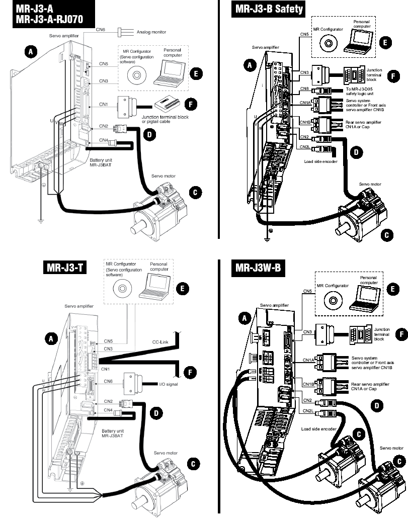
A. MR-J3 Amplifiers
B. Converter Unit (Required for 30KW ~ 55KW 200/400V amplifiers)
C. MR-J3 Servomotors
D. Cables and Connectors
E. Software and Manuals
F. System Options
MR-J3 Servomotors
|
Motor Series |
Rated Speed (Max. r/min) |
Rated Output Capacity (kW) |
Electromagnetic Brake Available |
Standards |
Protective Degree |
Features |
Application Examples |
||
|
EN |
UL / cUL |
||||||||
|
Small Capacity |
HF-KP |
3000 (6000) |
5 Types (200V) 0.05, 0.1, 0.2, 0.4, 0.75 |
x |
x |
x |
IP65 (*2) |
Low inertia: perfect for general industrial machines |
|
|
Ultra-low inertia: well suited for high frequency operation |
|
||||||||
|
Medium Capacity |
1000 (1500) |
6 Types (200V) 0.5, 0.85, 1.2, 2.0, 3.0, 4.2 |
x |
x |
x |
IP67 (*2) |
Medium inertia: suitable for variable applications three models from low to high-speed are available |
|
|
|
2000 (3000) |
7 Types (200V) 0.5, 1.0, 1.5, 2.0, 3.5, 5.0, 7.0 |
x |
x |
x |
IP67 (*2) |
||||
|
2000 (3000) |
5 Types (200V) 0.5, 1.0, 1.5, 2.0, 3.0 |
x |
x |
x |
IP65 (*2) |
Low inertia: perfect for general industrial machines |
|
||
|
3000 (4500) |
5 Types (200V) 1.0, 1.5, 2.0, 3.5, 5.0 |
x |
x |
x |
IP65 (*2) |
Ultra-low inertia: well suited for high-frequency |
|
||
|
Flat, Small/Medium Capacity |
2000 (3000: 0.75 ~ 2kW; 2500: 3.5, 5kW) |
5 Types (200V) 0.75, 1.5, 2.0, 3.5, 5.0 |
x |
x |
x |
IP65 (*2) |
Flat type: well suited for situations where the installation space is restricted |
|
|
|
Medium/Large Capacity |
HF-JP |
3000 (6000) |
7 Types (200V) 0.5, 0.75, 1.0, 1.5, 2.0, 3.5, 5.0 |
x |
- |
- |
IP67 |
Low inertia: |
|
|
1500 (3000) |
2 Types (200V) 11, 15 |
x |
- |
- |
IP67 |
|
|||
|
HA-LP |
1000 (1200) |
8 Types (200V) 6.0, 8.0, 12, 15, 20, 25, 30, 37 |
x (6.0 ~ 12kW only) |
x (*4) |
x (*4) |
IP44 (*2) |
Low inertia: suitable for variable applications three models from low to medium-speed are available. As a standard, 30kW and larger capacities are compatible with flange mounting or foot mounting |
|
|
|
1500 (2000) |
6 Types (200V) 7.0, 11, 15, 22, 30, 37 |
x (7.0 ~ 15kW only) |
x (*4) |
x (*4) |
IP44 (*2) |
||||
|
2000 (2000) |
7 Types (200V) 5.0, 7.0, 11, 15, 22, 30, 37 |
x (11 ~ 22kW only) |
x (*4) |
x (*4) |
IP44 (HA-LP 502/702 = IP65) (*2) |
||||
|
Third Party Motor |
Exlar Actuator models GSX20, GSX30, GSX40, GSX50, GSX60. Order directly through Exlar Corporation www.exlar.com Select Amplifiers and Cables from Mitsubishi. |
||||||||
Notes:
- “x” indicates the available product range.
- The shaft-through portion is excluded.
- Some motors from 15 to 25kW capacities can be mounted with the feet. Refer to the Motor Dimensions of this catalog.
- Some motors are under application for EN, UL, and cUL standards. Contact MEAU for more details.
(Example Part# = HF-SP102BK)
Not all options are available for every motor.
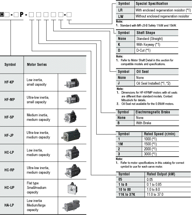
|
Stocked Motors |
|||||||||||||||||||||||||||||||||||||||||||||||
|
|
|
|||||||||||||||||||||||||||||||||||||||||||||
|
|
|
|||||||||||||||||||||||||||||||||||||||||||||
(Example Part# = HF-SP524BK)
Not all options are available for every motor.
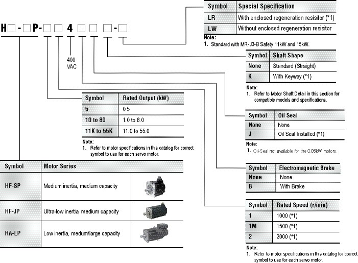
|
Stocked Motors |
|||||||||||||||||||||||||||||
|
|
||||||||||||||||||||||||||||
|
HF-KP Series 200V Servomotor Specifications
|
Servomotor Model HF-KP_ |
053(B) |
13(B) |
23(B) |
43(B) |
73(B) |
|
|
Servo Amplifier Model MR-J3-_-_ |
10A(1)(-RJ070)/BS(1)/T(1)/W-22B |
20A(1)(-RJ070)/BS(1)/ T(1)/W-22B/W-44B |
40A(1)(-RJ070)/BS(1)/ T(1)/W-44B/W-77B |
70A(-RJ070)/ |
||
|
Power Facility Capacity (kVA) (*1) |
0.3 |
0.3 |
0.5 |
0.9 |
1.3 |
|
|
Continuous Running Duty |
Rated Output (W) |
50 |
100 |
200 |
400 |
750 |
|
Rated Torque (N•m [oz•in]) |
0.16 (22.7) |
0.32 (45.3) |
0.64 (90.6) |
1.3 (184) |
2.4 (340) |
|
|
Maximum Torque (N•m [oz•in]) |
0.48 (68) |
0.95 (135) |
1.9 (269) |
3.8 (538) |
7.2 (1020) |
|
|
Rated Speed (r/min) |
3000 |
|||||
|
Maximum Speed (r/min) |
6000 |
|||||
|
Permissible Instantaneous Speed (r/min) |
6900 |
|||||
|
Power Rate at Continuous Rated Torque (kW/s) |
4.87 |
11.5 |
16.9 |
38.6 |
39.9 |
|
|
Rated Current (A) |
0.9 |
0.8 |
1.4 |
2.7 |
5.2 |
|
|
Maximum Current (A) |
2.7 |
2.4 |
4.2 |
8.1 |
15.6 |
|
|
Regenerative Braking Frequency (*2) (times/min) |
Refer to Manual |
Refer to Manual |
448 |
249 |
140 |
|
|
Moment Of Inertia |
Standard |
0.052 (0.284) |
0.088 (0.481) |
0.24 (1.31) |
0.42 (2.30) |
1.43 (7.82) |
|
With Electromagnetic Brake |
0.054 (0.295) |
0.090 (0.492) |
0.31 (1.69) |
0.50 (2.73) |
1.63 (8.91) |
|
|
Recommended Load / Motor Inertia Moment Ratio (*3) |
15 times maximum |
24 times maximum |
22 times maximum |
15 times maximum |
||
|
Speed/Position Detector |
18-bit encoder (Resolution per encoder/servomotor rotation: 262144p/rev) |
|||||
|
Attachments |
- |
Motors with an oil seal are available (HF-KP_J) |
||||
|
Insulation Class |
Class B |
|||||
|
Structure |
Totally enclosed non-ventilated (protection level: IP65) (*4) |
|||||
|
Environment |
Ambient Temperature |
0 to 40°C (32 to 104°F) (non-freezing), storage: -15 to 70°C (5 to 158°F) (non-freezing) |
||||
|
Ambient Humidity |
80% RH maximum (non-condensing), storage: 90% RH maximum (non-condensing) |
|||||
|
Atmosphere |
Indoors (no direct sunlight); no corrosive gas, inflammable gas, oil mist or dust |
|||||
|
Elevation / Vibration |
1000m or less above sea level/ X,Y:49m/s² |
|||||
|
Weight kg (lb) |
Standard |
0.35 (0.78) |
0.56 (1.3) |
0.94 (2.1) |
1.5 (3.3) |
2.9 (6.4) |
|
With Electromagnetic Brake |
0.65 (1.5) |
0.86 (1.9) |
1.6 (3.6) |
2.1 (4.7) |
3.9 (8.6) |
|
Notes:
- The power facility capacity varies depending on the power supply’s impedance.
- The regenerative braking frequency shows the permissible frequency for decelerating the motor without a load and the optional regeneration unit from the rated speed to a stop.
- Contact Mitsubishi if the load/motor of inertia moment ratio exceeds the value in the table.
- The shaft-through portion is excluded.
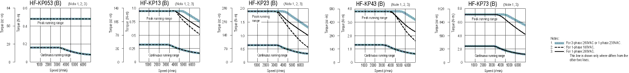
HF-MP Series 200V Servomotor Specifications
|
Servomotor Model HF-MP_ |
053(B) |
13(B) |
23(B) |
43(B) |
73(B) |
|
|
Servo Amplifier Model MR-J3-_-_ |
10A(1)(-RJ070)/ BS(1)/T(1)/W-22B |
20A(1)(-RJ070)/ BS(1)/ T(1)/W-22B/W-44B |
40A(1)(-RJ070)/ BS(1)/ T(1)W-44B/W-77B |
70A(-RJ070)/BS/ |
||
|
Power Facility Capacity (kVA) (*1) |
0.3 |
0.3 |
0.5 |
0.9 |
1.3 |
|
|
Continuous Running Duty |
Rated output (W) |
50 |
100 |
200 |
400 |
750 |
|
Rated torque (N•m [oz•in]) |
0.16 (22.7) |
0.32 (45.3) |
0.64 (90.6) |
1.3 (184) |
2.4 (340) |
|
|
Maximum Torque (N•m [oz•in]) |
0.48 (68) |
0.95 (135) |
1.9 (269) |
3.8 (538) |
7.2 (1020) |
|
|
Rated Speed (r/min) |
3000 |
|||||
|
Maximum Speed (r/min) |
6000 |
|||||
|
Permissible Instantaneous Speed (r/min) |
6900 |
|||||
|
Power Rate at Continuous Rated Torque (kW/s) |
13.3 |
31.7 |
46.1 |
111.6 |
95.5 |
|
|
Rated Current (A) |
1.1 |
0.9 |
1.6 |
2.7 |
5.6 |
|
|
Maximum Current (A) |
3.2 |
2.8 |
5.0 |
8.6 |
16.7 |
|
|
Regen Braking Frequency (*2) (times/min) |
Refer to Manual |
Refer to Manual |
1570 |
920 |
420 |
|
|
Moment of Inertia |
Standard |
0.019 (0.104) |
0.032 (0.175) |
0.088 (0.481) |
0.15 (0.82) |
0.60 (3.28) |
|
With Electromagnetic Brake |
0.025 (0.137) |
0.039 (0.213) |
0.12 (0.656) |
0.18 (0.984) |
0.70 (3.83) |
|
|
Recommended Load/Motor Inertia Moment Ratio |
30 times the servomotor’s inertia moment maximum (*3) |
|||||
|
Speed/Position Detector |
18-bit encoder (Resolution per encoder/servomotor rotation: 262144p/rev) |
|||||
|
Attachments |
- |
- Motors with an oil seal are available (HF-MP_J) |
||||
|
Insulation Class |
Class B |
|||||
|
Structure |
Totally enclosed non-ventilated (protection level: IP65) (*4) |
|||||
|
Environment |
Ambient Temperature |
0 to 40°C (32 to 104°F) (non-freezing), storage: -15 to 70°C (5 to 158°F) (non-freezing) |
||||
|
Ambient Humidity |
80% RH maximum (non-condensing), storage: 90% RH maximum (non-condensing) |
|||||
|
Atmosphere |
Indoors (no direct sunlight); no corrosive gas, inflammable gas, oil mist or dust |
|||||
|
Elevation / Vibration |
1000m or less above sea level / X, Y: 49m/s² |
|||||
|
Weight kg (lb) |
Standard |
0.35 (0.78) |
0.56 (1.3) |
0.94 (2.1) |
1.5 (3.3) |
2.9 (6.4) |
|
With electromagnetic brake |
0.65 (1.5) |
0.86 (1.9) |
1.6 (3.6) |
2.1 (4.7) |
3.9 (8.6) |
|
Notes:
- The power facility capacity varies depending on the power supply’s impedance.
- The regenerative braking frequency shows the permissible frequency for decelerating the motor without a load and the optional regeneration unit from the rated speed to a stop.
- Contact Mitsubishi if the load/motor of inertia moment ratio exceeds the value in the table.
- The shaft-through portion is excluded.
HF-MP Series 200V Servomotor Speed Torque Curves
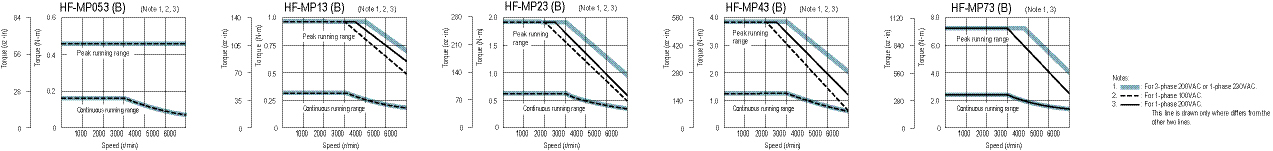
HF-SP 1000r/min Series 200V Servomotor Specifications
|
Servomotor Model HF-SP_ |
51(B) |
81(B) |
121(B) |
201(B) |
301(B) |
421(B) |
|
|
Servo Amplifier Model MR-J3-_-_ |
60A(-RJ070)/ |
100A(-RJ070)/ |
200A(-RJ070)/BS/T |
350A(-RJ070)/ |
500A(-RJ070)/ |
||
|
Power Facility Capacity (kVA) (*1) |
1.0 |
1.5 |
2.1 |
3.5 |
4.8 |
6.3 |
|
|
Continuous Running Duty |
Rated Output (kW) |
0.5 |
0.85 |
1.2 |
2.0 |
3.0 |
4.2 |
|
Rated Torque (N•m [oz•in]) |
4.77 (675) |
8.12 (1150) |
11.5 (1630) |
19.1 (2700) |
28.6 (4050) |
40.1 (5679) |
|
|
Maximum Torque (N•m [oz•in]) |
14.3 (2030) |
24.4 (3460) |
34.4 (4870) |
57.3 (8110) |
85.9 (12200) |
120 (17000) |
|
|
Rated Speed (r/min) |
1000 |
||||||
|
Maximum Speed (r/min) |
1500 |
||||||
|
Permissible Instantaneous Speed (r/min) |
1725 |
||||||
|
Power Rate at Continuous Rated Torque (kW/s) |
19.2 |
37.0 |
34.3 |
48.6 |
84.6 |
104 |
|
|
Rated Current (A) |
2.9 |
4.5 |
6.5 |
11 |
16 |
24 |
|
|
Maximum Current (A) |
8.7 |
13.5 |
19.5 |
33 |
48 |
72 |
|
|
Regenerative Braking Frequency (Times/Min) (*2) |
36 |
90 |
188 |
105 |
84 |
75 |
|
|
)] |
Standard |
11.9 (65.1) |
17.8 (97.3) |
38.3 (290) |
75.0 (410) |
97.0 (530) |
154 (842) |
|
With Electromagnetic Brake |
14.0 (76.5) |
20.0 (109) |
47.9 (262) |
84.7 (463) |
107 (585) |
164 (897) |
|
|
Recommended Load/Motor Inertia Moment Ratio |
15 times the servomotor’s inertia moment maximum (*3) |
||||||
|
Speed/Position Detector |
18-bit encoder (Resolution per encoder/servomotor rotation: 262144p/rev) |
||||||
|
Attachments |
Motors with an oil seal are available (HF-SP_J) |
||||||
|
Insulation Class |
Class F |
||||||
|
Structure |
Totally enclosed non-ventilated (protection level: IP67) (*4) |
||||||
|
Environment |
Ambient Temperature |
0 to 40°C (32 to 104°F) (non-freezing), storage: -15 to 70°C (5 to 158°F) (non-freezing) |
|||||
|
Ambient Humidity |
80% RH maximum (non-condensing), storage: 90% RH maximum (non-condensing) |
||||||
|
Atmosphere |
Indoors (no direct sunlight); no corrosive gas, inflammable gas, oil mist or dust |
||||||
|
Elevation / Vibration (*5) |
1000m or less above sea level X: 24.5m/s² Y: 24.5m/s² |
1000m or less above sea level X: 24.5m/s² Y: 49m/s² |
1000m or less above sea level X: 24.5m/s² Y: 29.4m/s² |
||||
|
Weight kg (lb) |
Standard |
6.5 (15) |
8.3 (19) |
12 (27) |
19 (42) |
22 (49) |
32 (71) |
|
With Electromagnetic Brake |
8.5 (19) |
10.3 (23) |
18 (40) |
25 (56) |
28 (62) |
38 (84) |
|
Notes:
- The power facility capacity varies depending on the power supply’s impedance.
- The regenerative braking frequency shows the permissible frequency for decelerating the motor without a load and the optional regeneration unit from the rated speed to a stop.
- Contact Mitsubishi if the load/motor of inertia moment ratio exceeds the value in the table.
- The shaft-through portion is excluded.
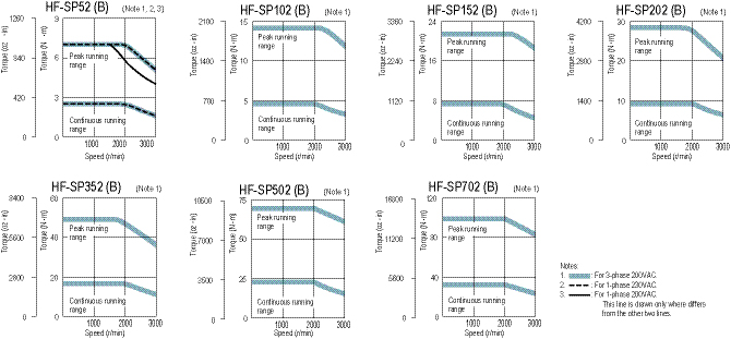
HF-SP 2000r/min Series 200V Servomotor Specifications
|
Servomotor Model HF-SP_ |
52(B) |
102(B) |
152(B) |
202(B) |
352(B) |
502(B) |
702(B) |
|
|
Servo Amplifier Model MR-J3-_-_ |
60A(-RJ070)/BS/T |
100A(-RJ070)/BS/T |
200A(-RJ070)/BS/T |
350A(-RJ070)/BS/T |
500A(-RJ070)/BS/T |
700A(-RJ070)/BS/T |
||
|
Power Facility Capacity (kVA) (*1) |
1.0 |
1.7 |
2.5 |
3.5 |
5.5 |
7.5 |
10 |
|
|
Continuous Running Duty |
Rated Output (kW) |
0.5 |
1.0 |
1.5 |
2.0 |
3.5 |
5.0 |
7.0 |
|
Rated Torque (N•m [oz•in]) |
2.39 (338) |
4.77 (675) |
7.16 (1010) |
9.55 (1350) |
16.7 (2360) |
23.9 (3380) |
33.4 (4730) |
|
|
Maximum Torque (N•m [oz•in]) |
7.16 (1010) |
14.3 (2020) |
21.5 (3040) |
28.6 (4050) |
50.1 (7090) |
71.6 (10100) |
100 (14200) |
|
|
Rated Speed (r/min) |
2000 |
|||||||
|
Maximum Speed (r/min) |
3000 |
|||||||
|
Permissible Instantaneous Speed (r/min) |
3450 |
|||||||
|
Power Rate Continuous Rated Torque (kW/s) |
9.34 |
19.2 |
28.8 |
23.8 |
37.2 |
58.8 |
72.5 |
|
|
Rated Current (A) |
2.9 |
5.3 |
8.0 |
10 |
16 |
24 |
33 |
|
|
Maximum Current (A) |
8.7 |
15.9 |
24 |
30 |
48 |
72 |
99 |
|
|
Regenerative Braking Frequency (times/min) (*2) |
60 |
62 |
152 |
71 |
33 |
37 |
31 |
|
|
Moment of inertia J (x10-4kg•m²) [J (oz•in²)] |
Standard |
6.1 (33.4) |
11.9 (65.1) |
17.8 (97.3) |
38.3 (209) |
75.0 (410) |
97.0 (530) |
154 (842) |
|
With Electromagnetic Brake |
8.3 (45.4) |
14.0 (76.5) |
20.0 (109) |
47.9 (262) |
84.7 (463) |
107 (585) |
164 (897) |
|
|
Recommended Load/Motor Inertia Moment Ratio |
15 times the servomotor’s inertia moment maximum (*3) |
|||||||
|
Speed/Position Detector |
18-bit encoder (Resolution per encoder/servomotor rotation: 262144 p/rev) |
|||||||
|
Attachments |
Motors with an oil seal are available (HF-SP_J) |
|||||||
|
Insulation Class |
Class F |
|||||||
|
Structure |
Totally enclosed non-ventilated (protection level: IP67) (*4) |
|||||||
|
Environment |
Ambient Temperature |
0 to 40°C (32 to 104°F) (non-freezing), storage: -15 to 70°C (5 to 158°F) (non-freezing) |
||||||
|
Ambient Humidity |
80% RH maximum (non-condensing), storage: 90% RH maximum (non-condensing) |
|||||||
|
Atmosphere |
Indoors (no direct sunlight); no corrosive gas, inflammable gas, oil mist or dust |
|||||||
|
Elevation / Vibration (*5) |
1000m or less above sea level X: 24.5m/s² Y: 24.5m/s² |
1000m or less above sea level X: 24.5m/s² Y: 49m/s² |
1000m or less above sea level X: 24.5m/s² Y: 29.4m/s² |
|||||
|
Weight kg (lb) |
Standard |
4.8 (11) |
6.5 (15) |
8.3 (19) |
12 (27) |
19 (42) |
22 (49) |
32 (71) |
|
With Electromagnetic Brake |
6.7 (15) |
8.5 (19) |
10.3 (23) |
18 (40) |
25 (56) |
28 (62) |
38 (84) |
|
Notes:
- The power facility capacity varies depending on the power supply’s impedance.
- The regenerative braking frequency shows the permissible frequency for decelerating the motor without a load and the optional regeneration unit from the rated speed to a stop.
- Contact Mitsubishi if the load/motor of inertia moment ratio exceeds the value in the table.
- The shaft-through portion is excluded.
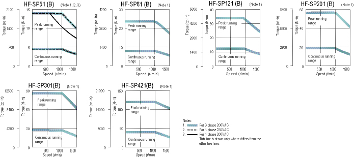
HF-SP 2000r/min Series 400V Servomotor Specifications
|
Servomotor Model HF-SP_ |
524(B) |
1024(B) |
1524(B) |
2024(B) |
3524(B) |
5024(B) |
7024(B) |
|
|
Servo Amplifier Model MR-J3-_-_ |
60A4(-RJ070)/BS4/T4 |
100A4(-RJ070)/BS4/T4 |
200A4(-RJ070)/BS4/T4 |
350A4(-RJ070)/ BS4/T4 |
500A4(-RJ070)/BS4/T4 |
700A4(-RJ070)/ BS4/T4 |
||
|
Power Facility Capacity (kVA) (*1) |
1.0 |
1.7 |
2.5 |
3.5 |
5.5 |
7.5 |
10 |
|
|
Continuous Running Duty |
Rated Output (kW) |
0.5 |
1.0 |
1.5 |
2.0 |
3.5 |
5.0 |
7.0 |
|
Rated Torque (N•m [oz•in]) |
2.39 (338) |
4.77 (675) |
7.16 (1010) |
9.55 (1350) |
16.7 (2360) |
23.9 (3380) |
33.4 (4730) |
|
|
Maximum Torque (N•m [oz•in]) |
7.16 (1010) |
14.3 (2020) |
21.5 (3040) |
28.6 (4050) |
50.1 (7090) |
71.6 (10100) |
100 (14200) |
|
|
Rated Speed (r/min) |
2000 |
|||||||
|
Maximum Speed (r/min) |
3000 |
|||||||
|
Permissible Instantaneous Speed (r/min) |
3450 |
|||||||
|
Power Rate Continuous Rated Torque (kW/s) |
9.34 |
19.2 |
28.8 |
23.8 |
37.2 |
58.8 |
72.5 |
|
|
Rated Current (A) |
1.5 |
2.9 |
4.1 |
5.0 |
8.4 |
12 |
16 |
|
|
Maximum Current (A) |
4.5 |
8.7 |
12 |
15 |
25 |
36 |
48 |
|
|
Regenerative Braking Freq. (times/min) (*2) |
90 |
46 |
154 |
72 |
37 |
34 |
28 |
|
|
Moment of inertia |
Standard |
6.1 (33.4) |
11.9 (65.1) |
17.8 (97.3) |
38.3 (209) |
75.0 (410) |
97.0 (530) |
154 (842) |
|
With Electromagnetic Brake |
8.3 (45.4) |
14.0 (76.5) |
20.0 (109) |
47.9 (262) |
84.7 (463) |
107 (585) |
164 (897) |
|
|
Recommended Load / Motor Inertia Moment Ratio |
15 times the servomotor’s inertia moment maximum (*3) |
|||||||
|
Speed/Position Detector |
18-bit encoder (Resolution per encoder/servomotor rotation: 262144 p/rev) |
|||||||
|
Attachments |
Motors with an oil seal are available (HF-SP_J) |
|||||||
|
Insulation Class |
Class F |
|||||||
|
Structure |
Totally enclosed non-ventilated (protection level: IP67) (*4) |
|||||||
|
Environment |
Ambient Temperature |
0 to 40°C (32 to 104°F) (non-freezing), storage: -15 to 70°C (5 to 158°F) (non-freezing) |
||||||
|
Ambient Humidity |
80% RH maximum (non-condensing), storage: 90% RH maximum (non-condensing) |
|||||||
|
Atmosphere |
Indoors (no direct sunlight); no corrosive gas, inflammable gas, oil mist or dust |
|||||||
|
Elevation / Vibration (*5) |
1000m or less above sea level X: 24.5m/s² Y: 24.5m/s² |
1000m or less above sea level X: 24.5m/s² Y: 49m/s² |
1000m or less above sea level X: 24.5m/s² Y: 29.4m/s² |
|||||
|
Weight kg (lb) |
Standard |
4.8 (11) |
6.7 (15) |
8.5 (19) |
13 (29) |
19 (42) |
22 (49) |
32 (71) |
|
With Electromagnetic Brake |
6.7 (15) |
8.6 (19) |
11 (25) |
19 (42) |
25 (56) |
28 (62) |
38 (84) |
|
Notes:
- The power facility capacity varies depending on the power supply’s impedance.
- The regenerative braking frequency shows the permissible frequency for decelerating the motor without a load and the optional regeneration unit from the rated speed to a stop.
- Contact Mitsubishi if the load/motor of inertia moment ratio exceeds the value in the table.
- The shaft-through portion is excluded.
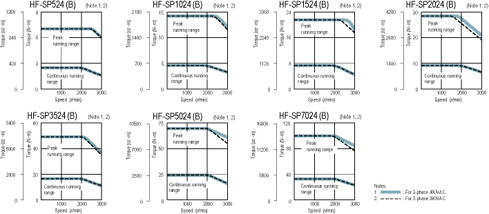
HC-LP Series 200V Servomotor Specifications
|
Servomotor Model HC-LP_ |
52(B) |
102(B) |
152(B) |
202(B) |
302(B) |
|
|
Servo Amplifier Model MR-J3-_-_ |
60A(-RJ070)/BS/T |
100A(-RJ070)/BS/T |
200A(-RJ070)/BS/T |
350A(-RJ070)/BS/T |
500A(-RJ070)/BS/T |
|
|
Power Facility Capacity (kVA) (*1) |
1.0 |
1.7 |
2.5 |
3.5 |
4.8 |
|
|
Continuous Running Duty |
Rated Output (kW) |
0.5 |
1.0 |
1.5 |
2.0 |
3.0 |
|
Rated Torque (N•m [oz•in]) |
2.39 (338) |
4.78 (677) |
7.16 (1010) |
9.55 (1350) |
14.3 (2020) |
|
|
Maximum Torque (N•m [oz•in]) |
7.16 (1010) |
14.4 (2040) |
21.6 (3060) |
28.5 (4040) |
42.9 (6070) |
|
|
Rated Speed (r/min) |
2000 |
|||||
|
Maximum Speed (r/min) |
3000 |
|||||
|
Permissible Instantaneous Speed (r/min) |
3450 |
|||||
|
Power Rate At Continuous Rated Torque (kW/s) |
18.4 |
49.3 |
79.8 |
41.5 |
56.8 |
|
|
Rated Current (A) |
3.2 |
5.9 |
9.9 |
14 |
23 |
|
|
Maximum Current (A) |
9.6 |
18 |
30 |
42 |
69 |
|
|
Regenerative Braking Frequency (Times/Min) (*2) |
115 |
160 |
425 |
120 |
70 |
|
|
Moment Of Inertia |
Standard |
3.10 (16.9) |
4.62 (25.3) |
6.42 (35.1) |
22.0 (120) |
36.0 (197) |
|
With Electromagnetic Brake |
5.20 (28.4) |
6.72 (36.7) |
8.52 (46.6) |
32.0 (175) |
46.0 (252) |
|
|
Recommended Load/Motor Inertia Moment Ratio |
10 times the servomotor’s inertia moment maximum (*3) |
|||||
|
Speed/Position Detector |
18-bit encoder (Resolution per encoder/servomotor rotation: 262144p/rev) |
|||||
|
Attachments |
Oil seal |
|||||
|
Insulation Class |
Class F |
|||||
|
Structure |
Totally enclosed non-ventilated (protection level: IP65) (*4) |
|||||
|
Environment |
Ambient Temperature |
0 to 40°C (32 to 104°F) (non-freezing), storage: -15 to 70°C (5 to 158°F) (non-freezing) |
||||
|
Ambient Humidity |
80% RH maximum (non-condensing), storage: 90% RH maximum (non-condensing) |
|||||
|
Atmosphere |
Indoors (no direct sunlight); no corrosive gas, inflammable gas, oil mist or dust |
|||||
|
Elevation / Vibration (*5) |
1000m or less above sea level X: 9.8m/s² Y: 24.5m/s² |
1000m or less above sea level X: 19.6m/s² Y: 49m/s² |
||||
|
Weight kg (lb) |
Standard |
6.5 (15) |
8.0 (18) |
10 (22) |
21 (47) |
28 (62) |
|
With Electromagnetic Brake |
9.0 (20) |
11 (25) |
13 (29) |
27 (60) |
34 (75) |
|
Notes:
- The power facility capacity varies depending on the power supply’s impedance.
- The regenerative braking frequency shows the permissible frequency for decelerating the motor without a load and the optional regeneration unit from the rated speed to a stop.
- Contact Mitsubishi if the load/motor of inertia moment ratio exceeds the value in the table.
- The shaft-through portion is excluded.
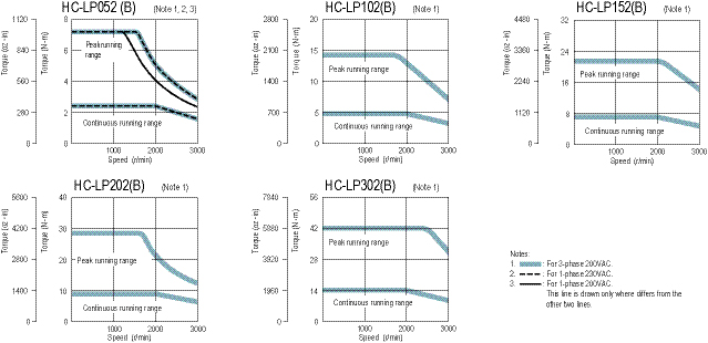
HC-RP Series 200V Servomotor Specifications
|
Servomotor Model HC-RP_ |
103(B) |
153(B) |
203(B) |
353(B) |
503(B) |
|
|
Servo Amplifier Model MR-J3-_-_ |
200A(-RJ070)/BS/T |
350A(-RJ070)/BS/T |
500A(-RJ070)/BS/T |
|||
|
Power Facility Capacity (kVA) (*1) |
1.7 |
2.5 |
3.5 |
5.5 |
7.5 |
|
|
Continuous Running Duty |
Rated Output (kW) |
1.0 |
1.5 |
2.0 |
3.5 |
5.0 |
|
Rated Torque (N•m [oz•in]) |
3.18 (450) |
4.78 (677) |
6.37 (902) |
11.1 (1570) |
15.9 (2250) |
|
|
Maximum Torque (N•m [oz•in]) |
7.95 (1130) |
11.9 (1690) |
15.9 (2250) |
27.9 (3950) |
39.7 (5620) |
|
|
Rated Speed (r/min) |
3000 |
|||||
|
Maximum Speed (r/min) |
4500 |
|||||
|
Permissible Instantaneous Speed (r/min) |
5175 |
|||||
|
Power Rate At Continuous Rated Torque (kW/s) |
67.4 |
120 |
176 |
150 |
211 |
|
|
Rated Current (A) |
6.1 |
8.8 |
14 |
23 |
28 |
|
|
Maximum Current (A) |
18 |
23 |
37 |
58 |
70 |
|
|
Regen Braking Frequency (times/min) (*2) |
1090 |
860 |
710 |
174 |
125 |
|
|
Moment Of inertia |
Standard |
1.50 (8.20) |
1.90 (10.4) |
2.30 (12.6) |
8.30 (45.4) |
12.0 (65.6) |
|
With Electromagnetic Brake |
1.85 (10.1) |
2.25 (12.3) |
2.65 (14.5) |
11.8 (64.5) |
15.5 (84.7) |
|
|
Recommended Load/Motor Inertia Moment Ratio |
5 times the servomotor’s inertia moment maximum (*3) |
|||||
|
Speed/Position Detector |
18-bit encoder (Resolution per encoder/servomotor rotation: 262144p/rev) |
|||||
|
Attachments |
Oil seal |
|||||
|
Insulation Class |
Class F |
|||||
|
Structure |
Totally enclosed non-ventilated (protection level: IP65) (*4) |
|||||
|
Environment |
Ambient Temperature |
0 to 40°C (32 to 104°F) (non-freezing), storage: -15 to 70°C (5 to 158°F) (non-freezing) |
||||
|
Ambient Humidity |
80% RH maximum (non-condensing), storage: 90% RH maximum (non-condensing) |
|||||
|
Atmosphere |
Indoors (no direct sunlight); no corrosive gas, inflammable gas, oil mist or dust |
|||||
|
Elevation/Vibration (*5) |
1000m or less above sea level X, Y: 24.5m/s² |
|||||
|
Weight kg (lb) |
Standard |
3.9 (8.6) |
5.0 (11) |
6.2 (14) |
12 (27) |
17 (38) |
|
With Electromagnetic Brake |
6.0 (14) |
7.0 (16) |
8.3 (19) |
15 (33) |
21 (47) |
|
Notes:
- The power facility capacity varies depending on the power supply’s impedance.
- The regenerative braking frequency shows the permissible frequency for decelerating the motor without a load and the optional regeneration unit from the rated speed to a stop.
- Contact Mitsubishi if the load/motor of inertia moment ratio exceeds the value in the table
- The shaft-through portion is excluded.
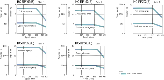
HC-UP Series 200V Servomotor Specifications
|
Servomotor Model HC-UP_ |
72(B) |
152(B) |
202(B) |
352(B) |
502(B) |
|
|
Servo Amplifier Model MR-J3-_-_ |
70A(-RJ070)/BS/T |
200A(-RJ070)/BS/T |
350A(-RJ070)/BS/T |
500A(-RJ070)/BS/T |
||
|
Power Facility Capacity (kVA) (*1) |
1.3 |
2.5 |
3.5 |
5.5 |
7.5 |
|
|
Continuous Running Duty |
Rated Output (kW) |
0.75 |
1.5 |
2.0 |
3.5 |
5.0 |
|
Rated Torque (N•m [oz•in]) |
3.58 (507) |
7.16 (1010) |
9.55 (1350) |
16.7 (2360) |
23.9 (3380) |
|
|
Maximum Torque (N•m [oz•in]) |
10.7 (1520) |
21.6 (3060) |
28.5 (4040) |
50.1 (7090) |
71.6 (10100) |
|
|
Rated Speed (r/min) |
2000 |
|||||
|
Maximum Speed (r/min) |
3000 |
2500 |
||||
|
Permissible Instantaneous Speed (r/min) |
3450 |
2875 |
||||
|
Power Rate At Continuous Rated Torque (kW/s) |
12.3 |
23.2 |
23.9 |
36.5 |
49.6 |
|
|
Rated Current (A) |
5.4 |
9.7 |
14 |
23 |
28 |
|
|
Maximum Current (A) |
16 |
29 |
42 |
69 |
84 |
|
|
Regen Braking Frequency (times/min) (*2) |
53 |
124 |
68 |
44 |
31 |
|
|
Moment Of Inertia |
Standard |
10.4 (56.9) |
22.1 (121) |
38.2 (209) |
76.5 (418) |
115 (629) |
|
With Electromagnetic Brake |
12.5 (68.3) |
24.2 (132) |
46.8 (256) |
85.1 (465) |
124 (678) |
|
|
Recommended Load / Motor Inertia Moment Ratio |
15 times the servomotor’s inertia moment maximum (*3) |
|||||
|
Speed / Position Detector |
18-bit encoder (Resolution per encoder/servomotor rotation: 262144p/rev) |
|||||
|
Attachments |
Oil seal |
|||||
|
Insulation Class |
Class F |
|||||
|
Structure |
Totally enclosed non-ventilated (protection level: IP65) (*4) |
|||||
|
Environment |
Ambient Temperature |
0 to 40°C (32 to 104°F) (non-freezing), storage: -15 to 70°C (5 to 158°F) (non-freezing) |
||||
|
Ambient Humidity |
80% RH maximum (non-condensing), storage: 90% RH maximum (non-condensing) |
|||||
|
Atmosphere |
Indoors (no direct sunlight); no corrosive gas, inflammable gas, oil mist or dust |
|||||
|
Elevation / Vibration (*5) |
1000m or less above sea level X, Y: 24.5m/s² |
1000m or less above sea level X: 24.5m/s² Y: 49m/s² |
||||
|
Weight kg (lb) |
Standard |
8.0 (18) |
11 (25) |
16 (36) |
20 (44) |
24 (53) |
|
With Electromagnetic Brake |
10 (22) |
13 (29) |
22 (49) |
26 (58) |
30 (67) |
|
Notes:
- The power facility capacity varies depending on the power supply’s impedance.
- The regenerative braking frequency shows the permissible frequency for decelerating the motor without a load and the optional regeneration unit from the rated speed to a stop.
- Contact Mitsubishi if the load/motor of inertia moment ratio exceeds the value in the table.
- The shaft-through portion is excluded.
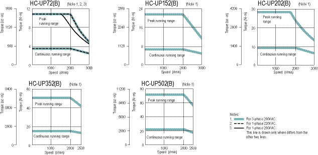
HF-JP Series 200V Servomotor Specifications
|
Servomotor Model HF-JP_ |
53(B) |
73(B) |
103(B) |
153(B) |
203(B) |
353(B) |
503(B) |
11K1M(B) |
15K1M(B) |
|
|
Servo Amplifier Model MR-J3-_-_ |
60A/BS/T |
70A/BS/T |
100A/BS/T |
200A/BS/T |
350A/BS/T |
500A/BS/T |
11KA/B/T-LR |
15KA/B/T-LR |
||
|
Power Supply Capacity (kVA) (*1) |
1.0 |
1.3 |
1.7 |
2.5 |
3.5 |
5.5 |
7.5 |
16 |
22 |
|
|
Continuous Running Duty |
Rated Output (kW) |
0.5 |
0.75 |
1.0 |
1.5 |
2.0 |
3.3 <3.5> (*7) |
5.0 |
11 |
15 |
|
Rated Torque (N•m [oz•in]) |
1.59 (225) |
2.39 (338) |
3.18 (450) |
4.77 (675) |
6.37 (902) |
10.5 (1490) (*7) <11.1 (1570)> |
15.9 (2250) |
70 (9910) |
95.5 (13500) |
|
|
Maximum Torque (N•m [oz•in]) |
4.77 (675) |
7.16 (1010) |
9.55 (1350) |
14.3 (2020) |
19.1 (2700) |
32.0 (4530) |
47.7 (6750) |
210 (29700) |
286 (40500) |
|
|
Rated Speed (r/min) |
3000 |
1500 |
||||||||
|
Maximum Speed (r/min) |
6000 |
3000 |
||||||||
|
Permissible Instantaneous Speed (r/min) |
6900 |
3450 |
||||||||
|
Power Rate At Continuous Rated Torque (kW/s) |
16.7 |
27.3 |
38.2 |
60.2 |
82.4 |
83.5 |
133 |
223 (204) |
290 (271) |
|
|
Rated Current (A) |
3.0 |
5.6 |
5.6 |
10.6 |
10.6 |
16.6 <17.6> |
27 |
60 |
76 |
|
|
Maximum Current (A) |
9.0 |
17 |
17 |
32 |
32 |
51 |
81 |
200 |
246 |
|
|
Regen Braking Frequency (times/min) (*2) |
67 |
98 |
76 |
271 |
206 |
73 |
68 |
143 |
162 |
|
|
Moment of Inertia J (x10-4 kg•m²) [J (oz•in²)] |
Standard |
1.52 (8.31) |
2.09 (11.4) |
2.65 (14.5) |
3.79 (20.7) |
4.92 (26.9) |
13.2 (72.2) |
19.0 (104) |
220 (1200) |
315 (1720) |
|
With Electromagnetic Brake |
2.02 (11.0) |
2.59 (14.2) |
3.15 (17.2) |
4.29 (23.5) |
5.42 (29.6) |
15.4 (84.2) |
21.2 (116) |
240 (1310) |
336 (1840) |
|
|
Recommended Load/Motor Inertia Moment Ratio |
Maximum of 10 times the servo motor's inertia moment (*3) |
|||||||||
|
Speed/Position Detector |
18-bit encoder (Resolution per encoder/servo motor rotation: 262144 p/rev) |
|||||||||
|
Attachments |
Oil seal |
|||||||||
|
Insulation Class |
Class F |
|||||||||
|
Structure |
Totally enclosed non-ventilated (IP code: IP67) (*4) |
|||||||||
|
Environment |
Ambient Temperature |
0 to 40°C (32 to 104°F) (non freezing), storage: -15 to 70°C (5 to 158°F) (non freezing) |
||||||||
|
Ambient Humidity |
80% RH maximum (non condensing), storage: 90% RH maximum (non condensing) |
|||||||||
|
Atmosphere |
Indoors (no direct sunlight); no corrosive gas, inflammable gas, oil mist or dust |
|||||||||
|
Elevation / Vibration (*5) |
1000m or less above sea level |
|||||||||
|
Vibration |
X: 24.5m/s² Y: 24.5m/s² |
|||||||||
|
Weight kg (lb) |
Standard |
3.0 (6.7) |
3.7 (8.2) |
4.5 (10) |
5.9 (13) |
7.5 (17) |
13 (29) |
18 (40) |
62 (140) |
86 (190) |
|
With Electromagnetic Brake |
4.4 (9.7) |
5.1 (12 ) |
5.9 (13) |
7.3 (16) |
8.9 (20) |
15 (33) |
20 (44) |
74 (165) |
97 (215) |
|
|
Maximally Increased Torque (*8) |
Compatible Servo Amplifier Model |
MR-J3-100A/ B/T-U100 |
MR-J3-200A/ B/T-U101 |
MR-J3-200A/ B/T-U102 |
MR-J3-350A/ B/T-U103 |
MR-J3-350A/ B/T-U104 |
MR-J3-500A/ B/T-U105 |
MR-J3-700A/ B/T-U106 |
- |
- |
|
Maximum Torque (N•m [oz•in]) |
6.37 (902) |
9.55 (1350) |
12.7 (1800) |
19.1 (2700) |
25.5 (3610) |
44.6 (6320) |
63.7 (9020) |
- |
- |
|
|
Maximum Current (A) |
12 |
23 |
23 |
43 |
43 |
71 |
108 |
- |
- |
|
Notes:
- The power supply capacity varies depending on the power supply’s impedance.
- The regenerative braking frequency shows the permissible frequency when the motor, without a load and the optional regeneration unit, decelerates from the rated speed to a stop.
- Contact Mitsubishi if the load to motor inertia moment ratio exceeds the value in the table.
- The shaft-through portion is excluded.
- In the environment where the servo motor is exposed to oil mist, oil and/or water, a standard specification servo motor may not be usable. Contact Mitsubishi for more details.
- Value indicated in < > is when connected to servo amplifier MR-J3-500A/B/T-U105.
- Use servo amplifier MR-J3-_A/B/T-U_ for maximally increased torque.
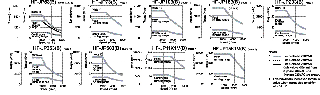
HF-JP Series 400V Servomotor Specifications
|
Servomotor Model HF-JP_ |
534(B) |
734(B) |
1034(B) |
1534(B) |
2034(B) |
3534(B) |
5034(B) |
11K1M4(B) |
15K1M4(B) |
|
|
Servo Amplifier Model MR-J3-_-_ |
60A4/BS4/T4 |
100A4/BS4/T4 |
200A4/BS4/4T |
350A4/BS4/T4 |
500A4/BS4/T4 |
11KA4/B4/T4-LR |
15KA4/B4/T4-LR |
|||
|
Power Supply Capacity (kVA) (*1) |
1.0 |
1.3 |
1.7 |
2.5 |
3.5 |
5.5 |
7.5 |
16 |
22 |
|
|
Continuous Running Duty |
Rated Output (kW) |
0.5 |
0.75 |
1.0 |
1.5 |
2.0 |
3.3 <3.5> |
5.0 |
11 |
15 |
|
Rated Torque (N•m [oz•in]) |
1.59 (225) |
2.39 (338) |
3.18 (450) |
4.77 (675) |
6.37 (902) |
10.5 (1490) <11.1 (1570)> |
15.9 (2250) |
70 (9910) |
95.5 (13500) |
|
|
Maximum Torque (N•m [oz•in]) |
4.77 (675) |
7.16 (1010) |
9.55 (1350) |
14.3 (2020) |
19.1 (2700) |
32.0 (4530) |
47.7 (6750) |
210 (29700) |
286 (40500) |
|
|
Rated Speed (r/min) |
3000 |
1500 |
||||||||
|
Maximum Speed (r/min) |
6000 |
3000 |
||||||||
|
Permissible Instantaneous Speed (r/min) |
6900 |
3450 |
||||||||
|
Power Rate At Continuous Rated Torque (kW/s) |
16.7 |
27.3 |
38.2 |
60.2 |
82.4 |
83.5 |
133 |
223 (204) |
290 (271) |
|
|
Rated Current (A) |
1.5 |
2.8 |
2.8 |
5.4 |
5.4 |
8.3 <8.8> |
14 |
32 |
38 |
|
|
Maximum Current (A) |
4.5 |
8.4 |
8.4 |
17 |
17 |
26 |
41 |
100 |
123 |
|
|
Regen Braking Frequency (times/min) (*2) |
99 |
72 |
56 |
265 |
203 |
75 |
68 |
143 |
162 |
|
|
Moment Of Inertia J (x10-4 kg•m²) |
Standard |
1.52 (8.31) |
2.09 (11.4) |
2.65 (14.5) |
3.79 (20.7) |
4.92 (26.9) |
13.2 (72.2) |
19.0 (104) |
220 (1200) |
315 (1720) |
|
With Electromagnetic Brake |
2.02 (11.0) |
2.59 (14.2) |
3.15 (17.2) |
4.29 (23.5) |
5.42 (29.6) |
15.4 (84.2) |
21.2 (116) |
240 (1310) |
336 (1840) |
|
|
Recommended Load/Motor Inertia Moment Ratio |
Maximum of 10 times the servo motor's inertia moment (*3) |
|||||||||
|
Speed/Position Detector |
18-bit encoder (Resolution per encoder/servo motor rotation: 262144 p/rev) |
|||||||||
|
Attachments |
Oil seal |
|||||||||
|
Insulation Class |
Class F |
|||||||||
|
Structure |
Totally enclosed non-ventilated (IP code: IP67) (*4) |
|||||||||
|
Environment (*6) |
Ambient Temperature |
0 to 40°C (32 to 104°F) (non freezing), storage: -15 to 70°C (5 to 158°F) (non freezing) |
||||||||
|
Ambient Humidity |
80% RH maximum (non condensing), storage: 90% RH maximum (non condensing) |
|||||||||
|
Atmosphere |
Indoors (no direct sunlight); no corrosive gas, inflammable gas, oil mist or dust |
|||||||||
|
Elevation / Vibration (*5) |
1000m or less above sea level |
|||||||||
|
Vibration |
X: 24.5m/s² Y: 24.5m/s² |
|||||||||
|
Weight kg (lb) |
Standard |
3.0 (6.7) |
3.7 (8.2) |
4.5 (10) |
5.9 (13) |
7.5 (17) |
13 (29) |
18 (40) |
62 (140) |
86 (190) |
|
With Electromagnetic Brake |
4.4 (9.7) |
5.1 (12 ) |
5.9 (13) |
7.3 (16) |
8.9 (20) |
15 (33) |
20 (44) |
74 (165) |
97 (215) |
|
|
Maximally Increased Torque (*8) |
Compatible Servo Amplifier Model |
MR-J3-100A4/B4/T4-U110 |
MR-J3-200A4/B4/T4-U111 |
MR-J3-200A4/B4/T4-U112 |
MR-J3-350A4/B4/T4-U113 |
MR-J3-350A4/B4/T4-U114 |
MR-J3-500A4/B4/T4-U115 |
MR-J3-700A4/B4/T4-U116 |
- |
- |
|
Maximum Torque (N·m [oz·in]) |
6.37 (902) |
9.55 (1350) |
12.7 (1800) |
19.1 (2700) |
25.5 (3610) |
44.6 (6320) |
63.7 (9020) |
- |
- |
|
|
Maximum Current (A) |
6 |
12 |
12 |
22 |
22 |
36 |
34 |
- |
- |
|
Notes:
- The power supply capacity varies depending on the power supply’s impedance.
- The regenerative braking frequency shows the permissible frequency when the motor, without a load and the optional regeneration unit, decelerates from the rated speed to a stop.
- Contact Mitsubishi if the load to motor inertia moment ratio exceeds the value in the table.
- The shaft-through portion is excluded.
- In the environment where the servo motor is exposed to oil mist, oil and/or water, a standard specification servo motor may not be usable. Contact Mitsubishi for more details.
- Value indicated in < > is when connected to servo amplifier MR-J3-500A/BS/T-U105.
- Use servo amplifier MR-J3-_A/BS/T-U_ for maximally increased torque.
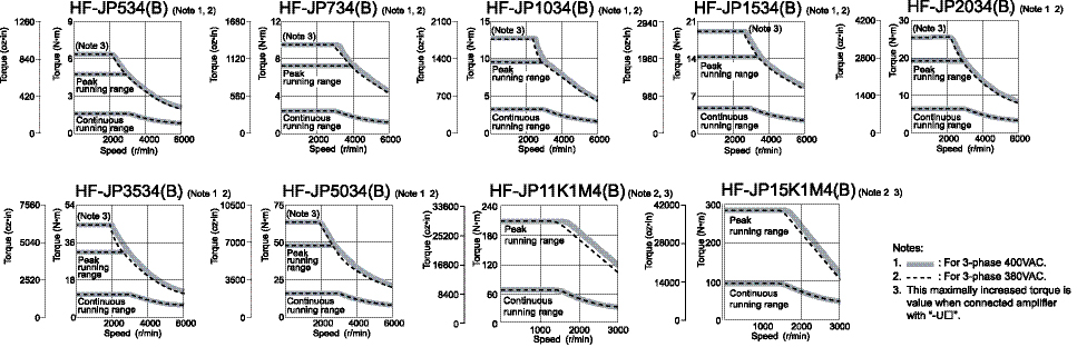
HA-LP 1000r/min Series 200V Servomotor Specifications
|
Servomotor Model HA-LP_ |
601(B) |
801(B) |
12K1(B) |
15K1 |
20K1 |
25K1 |
30K1 |
37K1 |
|
|
Servo Amplifier Model MR-J3-_-_ |
700A(-RJ070)/BS/T |
11KA(-RJ070)/BS/T |
15KA(-RJ070)/BS/T |
22KA(-RJ070)/BS/T |
DU30KA (-RJ070)/BS |
DU37KA (-RJ070)/BS |
|||
|
Power Facility Capacity (kVA) (*1) |
8.6 |
12 |
18 |
22 |
30 |
38 |
48 |
59 |
|
|
Continuous Running Duty |
Rated Output (kW) |
6.0 |
8.0 |
12 |
15 |
20 |
25 |
30 |
37 |
|
Rated Torque (N•m [oz•in]) |
57.3 (8110) |
76.4 (10800) |
115 (16300) |
143 (20200) |
191 (2700) |
239 (33800) |
286 (40500) |
353 (50000) |
|
|
Maximum Torque (N•m [oz•in]) |
172 (24400) |
229 (32400) |
344 (48700) |
415 (58800) |
477 (67500) |
597 (84500) |
716 (101000) |
883 (125000) |
|
|
Rated Speed (r/min) |
1000 |
||||||||
|
Maximum Speed (r/min) |
1200 |
||||||||
|
Permissible Instantaneous Speed (r/min) |
1380 |
||||||||
|
Power Rate At Continuous Rated Torque (kW/s) |
313 |
265 |
445 |
373 |
561 |
528 |
626 |
668 |
|
|
Rated Current (A) |
34 |
42 |
61 |
83 |
118 |
118 |
154 |
188 |
|
|
Maximum Current (A) |
102 |
126 |
183 |
249 |
295 |
295 |
385 |
470 |
|
|
Regen Braking Frequency (times/min) (*2) |
158 |
354 (*6) |
264 (*6) |
230 (*6) |
195 (*6) |
117 (*6) |
- |
- |
|
|
Moment Of Inertia J (x10-4 kg•m²) [J (oz•in²)] |
Standard |
105 (574) |
220 (1200) |
295 (1610) |
550 (3010) |
650 (3550) |
1080 (5900) |
1310 (7160) |
1870 (10200) |
|
With Electromagnetic Brake |
113 (618) |
293 (1600) |
369 (2020) |
- |
- |
- |
- |
- |
|
|
Recommended Load / Motor Inertia Moment Ratio |
10 times the servomotor’s inertia moment maximum (*3) |
||||||||
|
Speed / Position Detector |
18-bit encoder (Resolution per encoder/servomotor rotation: 262144p/rev) |
||||||||
|
Attachments |
Oil seal |
||||||||
|
Insulation Class |
Class F |
||||||||
|
Structure |
Totally enclosed ventilated (protection level: IP44) (*4) |
||||||||
|
Environment |
Ambient Temperature |
0 to 40°C (32 to 104°F) (non-freezing), storage: -15 to 70°C (5 to 158°F) (non-freezing) |
|||||||
|
Ambient Humidity |
80% RH maximum (non-condensing), storage: 90% RH maximum (non-condensing) |
||||||||
|
Atmosphere |
Indoors (no direct sunlight); no corrosive gas, inflammable gas, oil mist or dust |
||||||||
|
Elevation/ Vibration (*5) |
1000m or less above sea level X: 11.7m/s² Y: 29.4m/s² |
1000m or less above sea level X: 9.8m/s² Y: 9.8m/s² |
|||||||
|
Weight kg (lb) |
Standard |
55 (125) |
95 (210) |
115 (255) |
160 (355) |
180 (400) |
230 (510) |
250 (555) |
335 (740) |
|
With Electromagnetic Brake |
70 (155) |
130 (290) |
150 (335) |
- |
- |
- |
- |
- |
|
|
Cooling Fan Power |
Voltage, Frequency |
1-phase 200 to 220VAC/50Hz |
3-phase 200 to 230VAC 50/60Hz |
||||||
|
Input (W) |
42 (50Hz)/ |
62 (50Hz) / 76 (60Hz) |
65 (50Hz) / 85 (60Hz) |
120 (50Hz) / 175 (60Hz) |
|||||
|
Cooling Fan Rated Current (A) |
0.21(50Hz)/ |
0.18 (50Hz) / 0.17 (60Hz) |
0.20 (50Hz) / 0.22 (60Hz) |
0.65 (50Hz) / 0.80 (60Hz) |
|||||
Notes:
- The power facility capacity varies depending on the power supply’s impedance.
- The regenerative braking frequency shows the permissible frequency for decelerating the motor without a load and the optional regeneration unit from the rated speed to a stop.
- Contact Mitsubishi if the load/motor of inertia moment ratio exceeds the value in the table.
- The shaft-through portion is excluded.
- This applies when the GRZG400-_ Ω regeneration resistors are used as a standard accessory and parameter PA02 is changed with cooling fan (1.0m³/min, the _92x2 unit) installed.
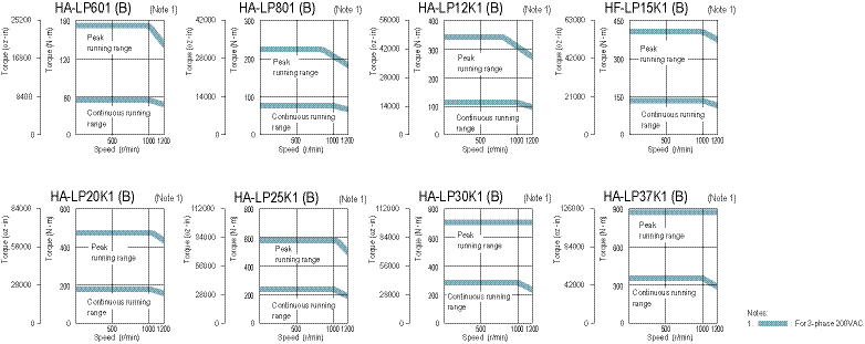
HA-LP 1000r/min Series 400V Servomotor Specifications
|
Servomotor Model HA-LP_ |
6014(B) |
8014(B) |
12K14(B) |
15K14 |
20K14 |
25K14 |
30K14 |
37K14 |
|
|
Servo Amplifier Model MR-J3-_-_ |
700A4(-RJ070)/BS4/T4 |
11KA4(-RJ070)/BS4/T4 |
15KA4(-RJ070)/BS4(-RJ006)/ T4 |
22KA4(-RJ070)/BS4/T4 |
DU30KA4(-RJ070)/BS4 |
DU37KA4 (-RJ070)/BS4 |
|||
|
Power Facility Capacity (kVA) (*1) |
8.6 |
12 |
18 |
22 |
30 |
38 |
48 |
59 |
|
|
Continuous Running Duty |
Rated Output (kW) |
6.0 |
8.0 |
12 |
15 |
20 |
25 |
30 |
37 |
|
Rated Torque |
57.3 (8110) |
76.4 (10800) |
115 (16300) |
143 (20200) |
191 (27000) |
239 (33800) |
286 (40500) |
353 (50000) |
|
|
Maximum Torque (N•m [oz•in]) |
172 (24400) |
229 (32400) |
344 (48700) |
415 (58800) |
477 (67500) |
597 (84500) |
716 (101000) |
883 (125000) |
|
|
Rated Speed (r/min) |
1000 |
||||||||
|
Maximum Speed (r/min) |
1200 |
||||||||
|
Permissible Instantaneous Speed (r/min) |
1380 |
||||||||
|
Power Rate At Continuous Rated Torque (kW/s) |
313 |
265 |
445 |
373 |
561 |
528 |
626 |
668 |
|
|
Rated Current (A) |
17 |
20 |
30 |
40 |
55 |
70 |
77 |
95 |
|
|
Maximum Current (A) |
51 |
60 |
90 |
120 |
138 |
175 |
193 |
238 |
|
|
Regen Braking Frequency (times/min) (*2) |
169 |
354 (*6) |
264 (*6) |
230 (*6) |
195 (*6) |
- |
- |
- |
|
|
Moment Of Inertia J (x10-4 kg•m²) [J (oz•in²)] |
Standard |
105 (574) |
220 (1200) |
295 (1610) |
550 (3010) |
650 (3550) |
1080 (5900) |
1310 (7160) |
1870 (10200) |
|
With Electromagnetic Brake |
113 (617.7) |
293 (1601.7) |
369 (2017.2) |
- |
- |
- |
- |
- |
|
|
Recommended Load/Motor Inertia Moment Ratio |
10 times the servomotor’s inertia moment maximum (*3) |
||||||||
|
Speed/Position Detector |
18-bit encoder (Resolution per encoder/servomotor rotation: 262144p/rev) |
||||||||
|
Attachments |
Oil seal |
||||||||
|
Insulation Class |
Class F |
||||||||
|
Structure |
Totally enclosed ventilated (protection level: IP44) (*4) |
||||||||
|
Environment |
Ambient Temperature |
0 to 40°C (32 to 104°F) (non-freezing), storage: -15 to 70°C (5 to 158°F) (non-freezing) |
|||||||
|
Ambient Humidity |
80% RH maximum (non-condensing), storage: 90% RH maximum (non-condensing) |
||||||||
|
Atmosphere |
Indoors (no direct sunlight); no corrosive gas, inflammable gas, oil mist or dust |
||||||||
|
Elevation / Vibration (*5) |
1000m or less above sea level X: 11.7m/s² Y: 29.4m/s² |
1000m or less above sea level X: 9.8m/s² Y: 9.8m/s² |
|||||||
|
Weight kg (lb) |
Standard |
55 (125) |
95 (210) |
115 (255) |
160 (355) |
180 (400) |
230 (510) |
250 (555) |
335 (740) |
|
With Electromagnetic Brake |
70 (155) |
130 (290) |
150 (335) |
- |
- |
- |
- |
- |
|
|
Cooling Fan Power |
Voltage, Frequency |
1-phase 200 to 220VAC/50Hz 1-phase 200 to 230VAC/60Hz |
3-phase 380 to 440VAC 50Hz 3-phase 380 to 480 VAC 60Hz |
3-phase 380 to 460VAC 50Hz; 3-phase 380 to 480VAC 60Hz |
|||||
|
Input (W) |
42 (50Hz)/ 54 (60Hz) |
62 (50Hz)/76 (60Hz) |
65 (50Hz)/85 (60Hz) |
110 (50Hz)/150 (60Hz) |
|||||
|
Cooling Fan Rated Current (A) |
0.21 (50Hz)/ 0.25 (60Hz) |
0.14 (50Hz)/0.11 (60Hz) |
0.12 (50Hz)/0.14 (60Hz) |
0.20 (50Hz)/0.22 (60Hz) |
|||||
Notes:
- The power facility capacity varies depending on the power supply’s impedance.
- The regenerative braking frequency shows the permissible frequency for decelerating the motor without a load and the optional regeneration unit from the rated speed to a stop.
- Contact Mitsubishi if the load/motor of inertia moment ratio exceeds the value in the table.
- The shaft-through portion is excluded.
- This applies when the GRZG400- _ Ω regeneration resistors are used as a standard accessory and parameter PA02 is changed with cooling fan (1.0m³/min, the _92 x 2 unit) installed.
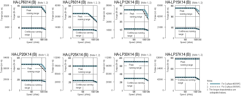
HA-LP 1500r/min Series 200V Servomotor Specifications
|
Servomotor Model HA-LP_ |
701M(B) |
11K1M(B) |
15K1M(B) |
22K1M |
30K1M |
37K1M |
|
|
Servo Amplifier Model MR-J3-_-_ |
700A(-RJ070)/BS/T |
11KA(-RJ070)/BS/T |
15KA(-RJ070)/BS/T |
22KA(-RJ070)/BS/T |
DU30KA(-RJ070)/BS |
DU37KA(-RJ070)/BS |
|
|
Power Facility Capacity (kVA) (*1) |
10 |
16 |
22 |
33 |
48 |
59 |
|
|
Continuous Running Duty |
Rated Output (kW) |
7.0 |
11 |
15 |
22 |
30 |
37 |
|
Rated Torque |
44.6 (6320) |
70.0 (9910) |
95.5 (13500) |
140 (19800) |
191 (27000) |
236 (33400) |
|
|
Maximum Torque (N•m [oz•in]) |
134 (19000) |
210 (29700) |
286 (40500) |
350 (49600) |
477 (67500) |
589 (83400) |
|
|
Rated Speed (r/min) |
1500 |
||||||
|
Maximum Speed (r/min) |
2000 |
||||||
|
Permissible Instantaneous Speed (r/min) |
2300 |
||||||
|
Power Rate at Continuous Rated Torque (kW/s) |
189 |
223 |
309 |
357 |
561 |
514 |
|
|
Rated Current (A) |
37 |
65 |
87 |
126 |
174 |
202 |
|
|
Maximum Current (A) |
111 |
195 |
261 |
315 |
435 |
505 |
|
|
Regen Braking Frequency (times/min) (*2) |
70 |
158 (*6) |
191 (*6) |
102 (*6) |
- |
- |
|
|
Moment Of inertia J (x10-4kg•m²) [J (oz•in²)] |
Standard |
105 (574) |
220 (1200) |
295 (1610) |
550 (3010) |
650 (3550) |
1080 (5900) |
|
With Electromagnetic Brake |
113 (618) |
293 (1600) |
369 (2020) |
- |
- |
- |
|
|
Recommended Load / Motor Inertia Moment Ratio |
10 times the servomotor’s inertia moment maximum (*3) |
||||||
|
Speed / Position Detector |
18-bit encoder (Resolution per encoder/servomotor rotation: 262144p/rev) |
||||||
|
Attachments |
Oil seal |
||||||
|
Insulation Class |
Class F |
||||||
|
Structure |
Totally enclosed ventilated (protection level: IP44) (*4) |
||||||
|
Environment |
Ambient Temperature |
0 to 40°C (32 to 104°F) (non-freezing), storage: -15 to 70°C (5 to 158°F) (non-freezing) |
|||||
|
Ambient Humidity |
80% RH maximum (non-condensing), storage: 90% RH maximum (non-condensing) |
||||||
|
Atmosphere |
Indoors (no direct sunlight); no corrosive gas, inflammable gas, oil mist or dust |
||||||
|
Elevation / Vibration (*5) |
1000m or less above sea level X: 11.7m/s² Y: 29.4m/s² |
1000m or less above sea level X: 9.8m/s² Y: 9.8m/s² |
|||||
|
Weight kg (lb) |
Standard |
55 (125) |
95 (210) |
115 (255) |
160 (355) |
180 (400) |
230 (510) |
|
With Electromagnetic Brake |
70 (155) |
130 (290) |
150 (335) |
- |
- |
- |
|
|
Cooling Fan Power |
Voltage, Frequency |
1-phase 200 to 220VAC / 50 Hz |
3-phase 200 to 230VAC 50/60Hz |
||||
|
Input (W) |
42 (50Hz) / 54 (60Hz) |
62 (50Hz) / 76 (60Hz) |
65 (50Hz) / 85 (60Hz) |
120 (50Hz) / 175 (60Hz) |
|||
|
Cooling Fan Rated Current (A) |
0.21 (50Hz) / 0.25 (60Hz) |
0.18 (50Hz) / 0.17 (60Hz) |
0.20 (50Hz) / 0.22 (60Hz) |
0.65 (50Hz) / 0.80 (60Hz) |
|||
Notes:
- The power facility capacity varies depending on the power supply’s impedance.
- The regenerative braking frequency shows the permissible frequency for decelerating the motor without a load and the optional regeneration unit from the rated speed to a stop.
- Contact Mitsubishi if the load/motor of inertia moment ratio exceeds the value in the table.
- The shaft-through portion is excluded.
- This applies when the GRZG400-_Ω regeneration resistors are used as a standard accessory and parameter PA02 is changed with cooling fan (1.0m³/min, the _92 x 2 unit) installed.
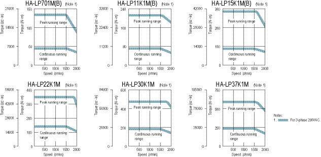
HA-LP 1500r/min Series 400V Servomotor Specifications
|
Servomotor Model HA-LP_ |
701M4(B) |
11K1M4(B) |
15K1M4(B) |
22K1M4 |
30K1M4 |
37K1M4 |
45K1M4 |
50K1M4 |
|
|
Servo Amplifier Model MR-J3-_-_ |
700A4(-RJ070)/BS4/T4 |
11KA4(-RJ070)/ BS4/T4 |
15KA4(-RJ070)/BS4/T4 |
22KA4(-RJ070)/ BS4/T4 |
DU30KA4 (-RJ070)/BS4 |
DU37KA4 (-RJ070)/BS4 |
DU45KA4 (-RJ070)/BS4 |
DU55KA4 (-RJ070)/BS4 |
|
|
Power Facility Capacity (kVA) (*1) |
10 |
16 |
22 |
33 |
48 |
59 |
71 |
80 |
|
|
Continuous Running Duty |
Rated Output (kW) |
7.0 |
11 |
15 |
22 |
30 |
37 |
45 |
50 |
|
Rated Torque |
44.6 (6320) |
70.0 (9910) |
95.5 (13500) |
140 (19800) |
191 (27000) |
236 (33400) |
286 (40500) |
318 (45000) |
|
|
Maximum Torque (N•m [oz•in]) |
134 (19000) |
210 (29700) |
286 (40500) |
350 (49600) |
477 (67500) |
589 (83400) |
716 (101000) |
796 (113000) |
|
|
Rated Speed (r/min) |
1500 |
||||||||
|
Maximum Speed (r/min) |
2000 |
||||||||
|
Permissible Instantaneous Speed (r/min) |
2300 |
||||||||
|
Power Rate At Continuous Rated Torque (kW/s) |
189 |
223 |
309 |
357 |
561 |
514 |
626 |
542 |
|
|
Rated Current (A) |
18 |
31 |
41 |
63 |
87 |
101 |
128 |
143 |
|
|
Maximum Current (A) |
54 |
93 |
123 |
158 |
218 |
253 |
320 |
358 |
|
|
Regen Braking Frequency (times/min) (*2) |
75 |
158 (*6) |
191 (*6) |
102 (*6) |
- |
- |
- |
- |
|
|
Moment Of Inertia J (x10-4 kg•m²) [J (oz•in²)] |
Standard |
105 (574) |
220 (1200) |
295 (1610) |
550 (3010) |
650 (3550) |
1080 (5900) |
1310 (7100) |
1870 (10200) |
|
With Electromagnetic Brake |
113 (618) |
293 (1600) |
369 (2020) |
- |
- |
- |
- |
- |
|
|
Recommended Load / Motor Inertia Moment Ratio |
10 times the servomotor’s inertia moment maximum (*3) |
||||||||
|
Speed / Position Detector |
18-bit encoder (Resolution per encoder/servomotor rotation: 262144p/rev) |
||||||||
|
Attachments |
Oil seal |
||||||||
|
Insulation class |
Class F |
||||||||
|
Structure |
Totally enclosed ventilated (protection level: IP44) (*4) |
||||||||
|
Environment |
Ambient Temperature |
0 to 40°C (32 to 104°F) (non-freezing), storage: -15 to 70°C (5 to 158°F) (non-freezing) |
|||||||
|
Ambient Humidity |
80% RH maximum (non-condensing), storage: 90% RH maximum (non-condensing) |
||||||||
|
Atmosphere |
Indoors (no direct sunlight); no corrosive gas, inflammable gas, oil mist or dust |
||||||||
|
Elevation / Vibration (*5) |
Y: 29.4m/s² |
1000m or less above sea level X: 9.8m/s² Y: 9.8m/s² |
|||||||
|
Weight kg (lb) |
Standard |
55 (125) |
95 (210) |
115 (255) |
160 (355) |
180 (400) |
230 (510) |
250 (555) |
335 (740) |
|
With Electromagnetic Brake |
70 (154.2) |
130 (290) |
150 (335) |
- |
- |
- |
- |
- |
|
|
Cooling Fan Power |
Voltage, Frequency |
1-phase 200 to 220VAC/50Hz |
3-phase 380 to 440VAC 50Hz |
3-phase 380 to 460VAC 50Hz |
|||||
|
Input (W) |
42 (50Hz)/ 54 (60Hz) |
62 (50Hz) / 76 (60Hz) |
65 (50Hz) / 85 (60Hz) |
110 (50Hz) / 150 (60Hz) |
|||||
|
Cooling Fan Rated Current (A) |
0.21 (50Hz)/ 0.25 (60Hz) |
0.14 (50Hz) / 0.11 (60Hz) |
0.12 (50Hz) / 0.14 (60Hz) |
0.20 (50Hz) / 0.22 (60Hz) |
|||||
Notes:
- The power facility capacity varies depending on the power supply’s impedance.
- The regenerative braking frequency shows the permissible frequency for decelerating the motor without a load and the optional regeneration unit from the rated speed to a stop.
- Contact Mitsubishi if the load/motor of inertia moment ratio exceeds the value in the table.
- The shaft-through portion is excluded.
- This applies when the GRZG400-_Ω regeneration resistors are used as a standard accessory and parameter PA02 is changed with cooling fan (1.0m³/min, the _92 x 2 unit) installed.
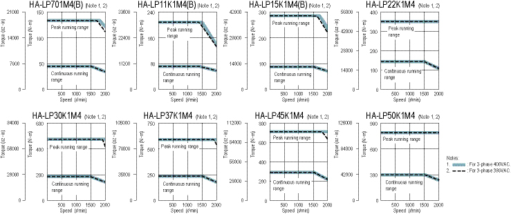
HA-LP 2000r/min Series 200V Servomotor Specifications
|
Servomotor Model HA-LP_ |
502 |
702 |
11K2(B) |
15K2(B) |
22K2(B) |
30K2 |
37K2 |
|
|
Servo Amplifier Model MR-J3-_-_ |
500A(-RJ070)/ BS/T |
700A(-RJ070)/ BS/T |
11KA(-RJ070)/ BS/T |
15KA(-RJ070)/ BS/T |
22KA(-RJ070)/ BS/T |
DU30KA(-RJ070)/BS |
DU37KA(-RJ070)/BS |
|
|
Power Facility Capacity (kVA) (*1) |
7.5 |
10.0 |
16 |
22 |
33 |
48 |
59 |
|
|
Continuous Running Duty |
Rated Output (kW) |
5.0 |
7.0 |
11 |
15 |
22 |
30 |
37 |
|
Rated Torque (N•m [oz•in]) |
23.9 (3380) |
33.4 (4730) |
52.5 (7430) |
71.6 (10100) |
105 (14900) |
143 (20200) |
177 (25100) |
|
|
Maximum Torque (N•m [oz•in]) |
71.6 (10100) |
100 (14200) |
158 (22400) |
215 (30400) |
263 (37200) |
358 (50700) |
442 (62600) |
|
|
Rated Speed (r/min) |
2000 |
|||||||
|
Maximum Speed (r/min) |
2000 |
|||||||
|
Permissible Instantaneous Speed (r/min) |
2300 |
|||||||
|
Power Rate At Continuous Rated Torque (kW/s) |
77.2 |
118 |
263 |
233 |
374 |
373 |
480 |
|
|
Rated Current (A) |
25 |
34 |
63 |
77 |
112 |
166 |
204 |
|
|
Maximum Current (A) |
75 |
102 |
189 |
231 |
280 |
415 |
510 |
|
|
Regen Braking Frequency (times/min) (*2) |
50 |
50 |
186 (*6) |
144 (*6) |
107 (*6) |
- |
- |
|
|
Moment Of Inertia J (x10-4 kg•m²) [J (oz•in²)] |
Standard |
74.0 (405) |
94.2 (515) |
105 (574) |
220 (1200) |
295 (1610) |
550 (3010) |
650 (3550) |
|
With Electromagnetic Brake |
- |
- |
113 (618) |
293 (1600) |
369 (2020) |
- |
- |
|
|
Recommended Load/Motor Inertia Moment Ratio |
10 times the servomotor’s inertia moment maximum (*3) |
|||||||
|
Speed/Position Detector |
18-bit encoder (Resolution per encoder/servomotor rotation: 262144p/rev) |
|||||||
|
Attachments |
Oil seal |
|||||||
|
Insulation Class |
Class F |
|||||||
|
Structure |
Totally enclosed non-ventilated (protection level: IP65) (*4) |
Totally enclosed ventilated (protection level: IP44) (*4) |
||||||
|
Environment |
Ambient Temperature |
0 to 40°C (32 to 104°F) (non-freezing), storage: -15 to 70°C (5 to 158°F) (non-freezing) |
||||||
|
Ambient Humidity |
80% RH maximum (non-condensing), storage: 90% RH maximum (non-condensing) |
|||||||
|
Atmosphere |
Indoors (no direct sunlight); no corrosive gas, inflammable gas, oil mist or dust |
|||||||
|
Elevation / Vibration |
1000m or less above sea level X: 11.7m/s² Y: 29.4m/s² |
1000m or less above sea level X: 9.8m/s² Y: 9.8m/s² |
||||||
|
Weight kg (lb) |
Standard |
28 (62) |
35 (78) |
55 (125) |
95 (210) |
115 (255) |
160 (355) |
180 (400) |
|
With Electromagnetic Brake |
- |
- |
70 (155) |
130 (290) |
150 (335) |
- |
- |
|
|
Cooling Fan Power |
Voltage, Frequency (*5) |
- |
- |
1-phase 200 to 220 VAC/50Hz 1-phase 200 to 230 VAC/60Hz |
3-phase 200 to 230VAC 50/60Hz |
|||
|
Input (W) |
- |
- |
42 (50Hz) / 54 (60Hz) |
62 (50Hz) / 76 (60Hz) |
65 (50Hz) / 85 (60Hz) |
|||
|
Cooling Fan Rated Current (A) |
- |
- |
0.21 (50Hz)/ 0.25 (60Hz) |
0.18 (50Hz) / 0.17 (60Hz) |
0.20 (50Hz) / 0.22 (60Hz) |
|||
Notes:
- The power facility capacity varies depending on the power supply’s impedance.
- The regenerative braking frequency shows the permissible frequency for decelerating the motor without a load and the optional regeneration unit from the rated speed to a stop.
- Contact Mitsubishi if the load/motor of inertia moment ratio exceeds the value in the table.
- The shaft-through portion is excluded.
- This applies when the GRZG400-_Ω regeneration resistors are used as a standard accessory and parameter PA02 is changed with cooling fan (1.0m³/min, the _92 x 2 unit) installed.
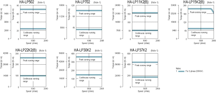
HA-LP 2000r/min Series 400V Servomotor Specifications
|
Servomotor Model HA-LP_ |
11K24(B) |
15K24(B) |
22K24(B) |
30K24 |
37K24 |
45K24 |
55K24 |
|
|
Servo Amplifier Model MR-J3-_-_ |
11KA4(-RJ070)/ BS4/T4 |
15KA4(-RJ070)/BS4/T4 |
22KA4(-RJ070)/BS4/T4 |
DU30KA4/BS4 |
DU37KA4/BS4 |
DU45KA4/BS4 |
DU55KA4/BS4 |
|
|
Power Facility Capacity (kVA) (*1) |
16 |
22 |
33 |
48 |
59 |
71 |
87 |
|
|
Continuous Running Duty |
Rated Output (kW) |
11 |
15 |
22 |
30 |
37 |
45 |
55 |
|
Rated Torque |
52.5 (7430) |
71.6 (10100) |
105 (14900) |
143 (20200) |
177 (25100) |
215 (30400) |
263 (37200) |
|
|
Maximum Torque (N•m [oz•in]) |
158 (22400) |
215 (30400) |
263 (37200) |
358 (50700) |
442 (62600) |
537 (76000) |
657 (93000) |
|
|
Rated Speed (r/min) |
2000 |
|||||||
|
Maximum Speed (r/min) |
2000 |
|||||||
|
Permissible Instantaneous Speed (r/min) |
2300 |
|||||||
|
Power Rate At Continuous Rated Torque (kW/s) |
263 |
233 |
374 |
373 |
480 |
427 |
526 |
|
|
Rated Current (A) |
32 |
40 |
57 |
83 |
102 |
131 |
143 |
|
|
Maximum Current (A) |
96 |
120 |
143 |
208 |
255 |
328 |
358 |
|
|
Regen. Braking Frequency |
186 (*6) |
144 (*6) |
107 (*6) |
- |
- |
- |
- |
|
|
Moment of Inertia J (x10-4 kg•m²) [J (oz•in²)] |
Standard |
105 (574) |
220 (1200) |
295 (1610) |
550 (3010) |
650 (3550) |
1080 (5900) |
1310 (7160) |
|
With Electromagnetic Brake |
113 (618) |
293 (1600) |
369 (2020) |
- |
- |
- |
- |
|
|
Recommended Load / Motor Inertia Moment Ratio |
10 times the servomotor’s inertia moment maximum (*3) |
|||||||
|
Speed / Position Detector |
18-bit encoder (Resolution per encoder/servomotor rotation: 262144p/rev) |
|||||||
|
Attachments |
Oil seal |
|||||||
|
Insulation Class |
Class F |
|||||||
|
Structure |
Totally enclosed ventilated (protection level: IP44) (*4) |
|||||||
|
Environment |
Ambient Temperature |
0 to 40°C (32 to 104°F) (non-freezing), storage: -15 to 70°C (5 to 158°F) (non-freezing) |
||||||
|
Ambient Humidity |
80% RH maximum (non-condensing), storage: 90% RH maximum (non-condensing) |
|||||||
|
Atmosphere |
Indoors (no direct sunlight); no corrosive gas, inflammable gas, oil mist or dust |
|||||||
|
Elevation / Vibration (*5) |
1000m or less above sea level X: 11.7m/s² Y: 29.4m/s² |
1000m or less above sea level X: 9.8m/s² Y: 9.8m/s² |
||||||
|
Weight kg (lb) |
Standard |
55 (125) |
95 (210) |
115 (255) |
160 (355) |
180 (400) |
230 (510) |
250 (555) |
|
With Electromagnetic Brake |
70 (155) |
130 (290) |
150 (335) |
- |
- |
- |
- |
|
|
Cooling Fan Power |
Voltage, Frequency |
1-phase 200 to 220 VAC / 50Hz |
3-phase 380 to 440VAC 50Hz |
3-phase 380 to 460VAC 50Hz |
||||
|
Input (W) |
42 (50Hz) / 54 (60Hz) |
62 (50Hz) / 76 (60Hz) |
65 (50Hz) / 85 (60Hz) |
110 (50Hz) / 150 (60Hz) |
||||
|
Cooling Fan Rated Current (A) |
0.21 (50Hz) / 0.25 (60Hz) |
0.14 (50Hz) / 0.11 (60Hz) |
0.12 (50Hz) / 0.14 (60Hz) |
0.20 (50Hz) / 0.22 (60Hz) |
||||
Notes:
- The power facility capacity varies depending on the power supply’s impedance.
- The regenerative braking frequency shows the permissible frequency for decelerating the motor without a load and the optional regeneration unit from the rated speed to a stop.
- Contact Mitsubishi if the load/motor of inertia moment ratio exceeds the value in the table.
- The shaft-through portion is excluded.
- This applies when the GRZG400-_Ω regeneration resistors are used as a standard accessory and parameter PA02 is changed with cooling fan (1.0m³/min, the _92x2 unit) installed.
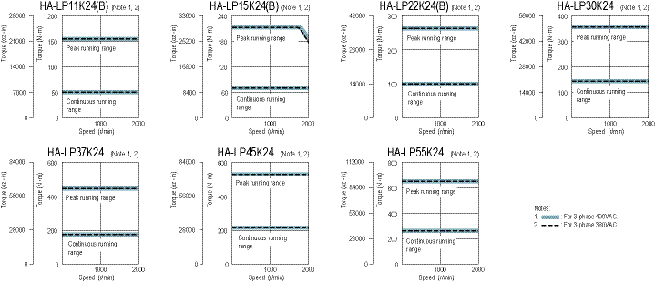
MR-J3 Motor Shaft Details and Servomotor Dimensions
D-Cut Shaft (50W & 100W Motors Only)
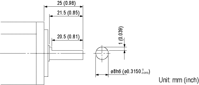
Keyway With Key Included

|
Motor Model |
Capacity (W) |
Variable Dimensions |
||||||||
|
T |
S |
R |
Q |
W |
QK |
QL |
U |
Y |
||
|
HF-KP_K |
200, 400 |
5 |
14h6 (0.554) |
30 (1.18) |
27 (1.06) |
5 |
20 (0.79) |
3 |
3 |
M4 Depth 15 (0.59) |
|
750 |
6 |
19h6 (0.7480) |
40 (1.57) |
37 (1.46) |
6 |
25 (0.98) |
5 |
3.5 (0.14) |
M5 Depth 20 (0.79) |
|
HF-SP / HF-JP / HC-LP / HC-RP/ HC-UP / HA-LP Series
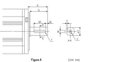
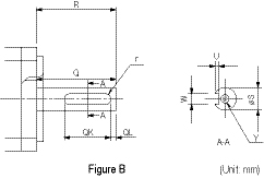
Keyway With No Key Supplied (Customer must supply key or order key part separately below)
|
Motor Model |
Capacity (kW) |
Variable Dimensions mm (in) |
Fig. |
Key Dimensions |
Key Model Number |
Stocked Item |
||||||||
|
S |
R |
Q |
W |
QK |
QL |
U |
r |
Y |
||||||
|
HF-SP_K |
0.5~1.5 |
) |
55 |
50 |
) |
36 |
5 |
) |
4 |
M8 |
A |
8x7x28 |
MTR KEY 8-7-28 |
S |
|
2.0~7.0 |
) |
79 |
75 |
) |
55 |
5 |
) |
5 |
10x8x45 |
MTR KEY 10-8-45 |
S |
|||
|
HC-RP_K |
1.0, 1.5, 2.0 |
) |
45 |
40 |
) |
25 |
5 |
) |
4 |
8x7x16 |
MTR KEY 8-7-16 |
S |
||
|
3.5, 5.0 |
) |
63 |
58 |
) |
53 |
3 |
) |
4 |
8x7x45 |
MTR KEY 8-7-45 |
S |
|||
|
HC-UP_K |
0.75 |
) |
55 |
50 |
) |
42 |
3 |
) |
3 |
6x6x36 |
MTR KEY 6-6-36 |
S |
||
|
1.5 |
) |
55 |
50 |
) |
40 |
3 |
) |
4 |
8x7x36 |
MTR KEY 8-7-36 |
S |
|||
|
2.0, 3.5, 5.0 |
) |
65 |
60 |
) |
50 |
5 |
) |
5 |
10x8x45 |
MTR KEY 10-8-45 |
S |
|||
|
HF-JP_K |
0.5~2.0 |
16h6 |
40 |
30 |
25 |
2 |
2.5 |
M4 |
- |
- |
- |
|||
|
3.5, 5 |
) |
55 |
50 |
) |
36 |
5 |
) |
4 (0.16) |
M8 |
8x7x28 |
MTR KEY 8-7-28 |
S |
||
|
11, 15 |
) |
116 (4.57) |
110 |
) |
90 |
5 |
) |
8 |
M10 |
- |
- |
- |
||
Keyway With No Key Supplied (Customer must supply key)
|
Motor Model (HA-LP_K) |
Variable Dimensions mm (in) |
Fig. |
Key Model Number |
||||||||
|
S |
R |
Q |
W |
QK |
QL |
U |
r |
Y |
|||
|
601, 6014, 701M, 701M4, 502, 702, 11K2, 11K24 |
) |
85 |
80 |
) |
70 |
5 |
) |
6 |
Same as Standard motor’s straight shaft. |
A |
(N/A) Key to be supplied by customer. |
|
801, 12K1, 8014, 12K14, 11K1M, 15K1M, 11K1M4, 15K1M4, 15K2, 22K2, 15K24, 22K24 |
) |
110 |
100 |
) |
90 |
5 |
) |
8 |
|||
|
15K1, 20K1, 15K14, 20K14, 22K1M, 30K1M, 22K1M4, 30K1M4, 30K2, 37K2, 30K24, 37K24 |
) |
140 |
140 |
) |
128 |
6 |
) |
9 |
B |
||
|
25K1, 30K1, 25K14, 30K14, 37K1M, 37K1M4, 45K1M4, 45K24, 55K24 |
) |
140 |
140 |
) |
128 |
6 |
) |
9 |
|||
|
37K1, 37K14, 50K1M4 |
) |
170 |
170 |
) |
147 |
11 |
) |
11 |
|||
Note: Not all key sizes are available to order from MEAU. If a key part is not listed, customer must supply.
HF-KP / HF-MP Series
HF-KP053(B), HF-KP13(B)
HF-MP053(B), HF-MP13(B)
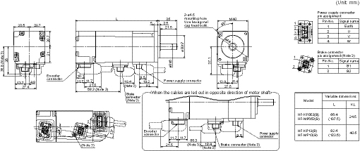
HF-KP23(B), HF-KP43(B)
HF-MP23(B), HF-MP43(B)
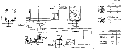
HF-KP73(B)
HF-MP73(B)
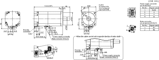
Notes:
- Use a friction coupling to fasten a load.
- Dimensions inside ( ) are for the models with an electromagnetic brake.
- Only for the models with an electromagnetic brake. The electromagnetic brake terminals (B1, B2) do not have the polarity.
- For dimensions where there is no tolerance listed, use general tolerance.
- Dimensions for motors with an oil seal (HF-MP_J and HF-KP_J) are different from the above. Contact Mitsubishi for details.
HF-SP51(B), HF-SP81(B)
HF-SP52(B) to HF-SP152(B), HF-SP524(B) to HF-SP152(B)
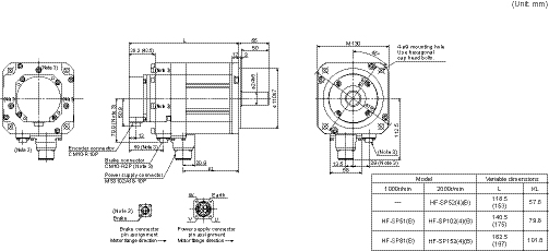
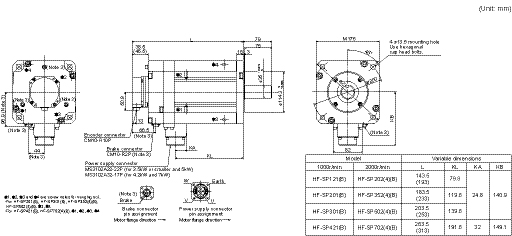
HF-SP121(B) to HF-SP421(B)
HF-SP202(B) to HF-SP702(B), HF-SP2024(B) to HF-SP7024(B) HF-MP73(B)
Notes:
- Use a friction coupling to fasten a load.
- Dimensions inside ( ) are for the models with an electromagnetic brake.
- Only for the models with an electromagnetic brake. The electromagnetic brake terminals do not have the polarity.
- For dimensions where there is no tolerance listed, use general tolerance.
HF-JP53(B), HF-JP73(B), HF-JP103(B), HF-JP153(B), HF-JP203(B)
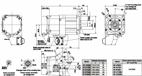
HF-JP353(B), HF-JP503(B)
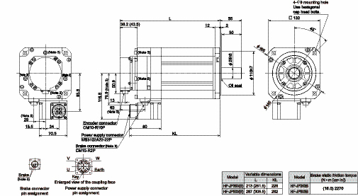
Notes:
- Use a friction coupling to fasten a load.
- Dimensions inside ( ) are for the models with an electromagnetic brake.
- Only for the models with an electromagnetic brake. The electromagnetic brake terminals do not have polarity.
- For dimensions where there is no tolerance listed, use general tolerance.
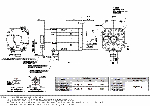
HF-JP11K1M(B), HF-JP15K1M(B), HF-JP11K1M4(B), HF-JP15K1M4(B)
HF-JP534(B), HF-JP734(B), HF-JP1034(B), HF-JP1534(B), HF-JP2034(B)
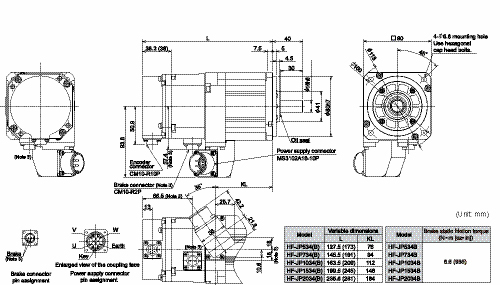
HF-JP3534(B), HF-JP5034(B)
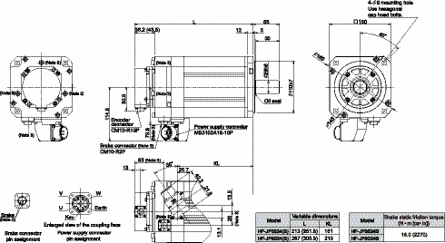
HC-LP52(B) to HC-LP152(B)
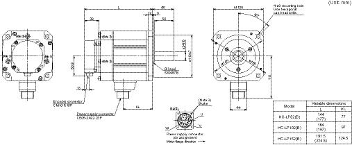
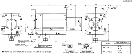
HC-LP202(B), HC-LP302(B)
Notes:
- Use a friction coupling to fasten a load.
- Dimensions inside ( ) are for the models with an electromagnetic brake.
- Only for the models with an electromagnetic brake. The electromagnetic brake terminals do not have polarity.
- For dimensions where there is no tolerance listed, use general tolerance.
HC-RP103(B) to HC-RP203(B)
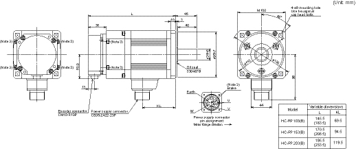
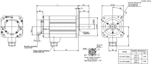
HC-RP353(B), HC-RP503(B)
Notes:
- Use a friction coupling to fasten a load.
- Dimensions inside ( ) are for the models with an electromagnetic brake.
- Only for the models with an electromagnetic brake. The electromagnetic brake terminals do not have the polarity.
- For dimensions where there is no tolerance listed, use general tolerance.
HC-UP72(B), HC-UP152(B)
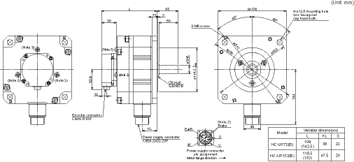
HC-UP202(B) to HC-UP502(B)
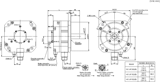
Notes:
- Use a friction coupling to fasten a load.
- Dimensions inside ( ) are for the models with an electromagnetic brake.
- Only for the models with an electromagnetic brake. The electromagnetic brake terminals do not have the polarity.
- For dimensions where there is no tolerance listed, use general tolerance.
HA-LP502
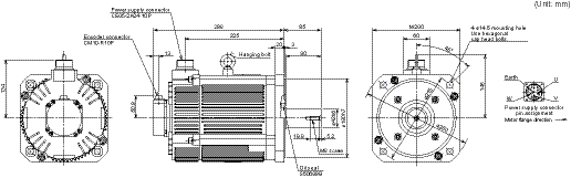
Notes:
- Use a friction coupling to fasten a load.
- For dimensions where there is no tolerance listed, use general tolerance
HA-LP702
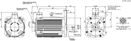
Notes:
- Use a friction coupling to fasten a load.
- For dimensions where there is no tolerance listed, use general tolerance
HA-LP601(B), HA-LP6014(B)
HA-LP701M(B), HA-LP701M4(B)
HA-LP11K2(B), HA-LP11K24(B)
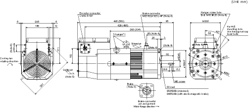
Notes:
- When using the motor without the hanger, plug the threaded hole with a bolt of M10 X 20 or shorter.
- The terminal block on the terminal box housing consists of M6 screws for the motor power supply (U, V, W), and M4 screws for the cooling fan (BU, BV) and for the thermal protector (OHS1, OHS2).
HA-LP801(B), HA-LP12K1(B), HA-LP8014(B) (*7), HA-LP12K14(B)
HA-LP11K1M(B), HA-LP15K1M(B), HA-LP11K1M4(B) (*7), HA-LP15K1M4(B)
HA-LP15K2(B), HA-LP22K2(B), HA-LP15K24(B), HA-LP22K24(B)
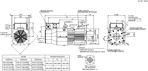
Notes:
- When using the motor without the hanger, plug the threaded hole with a bolt of M12 X 20 or shorter.
- The terminal block on the terminal box housing consists of M8 screws for the motor power supply (U, V, W), and M4 screws for the cooling fan (BU, BV, BW) and for the thermal protector (OHS1, OHS2).
Notes:
- Use a friction coupling to fasten a load.
- For dimensions where there is no tolerance listed, use general tolerance.
- Dimensions inside ( ) are for the models with an electromagnetic brake.
- Only for the models with an electromagnetic brake. The electromagnetic brake terminals do not have polarity.
- Leave a clearance of at least 100mm between the motor’s suction side and wall.
- Make sure that oil, water and dust, etc., will not enter the motor from the lead-in hole.
- Contact your dealer for the delivery schedule or the compatible servo amplifier’s software version.
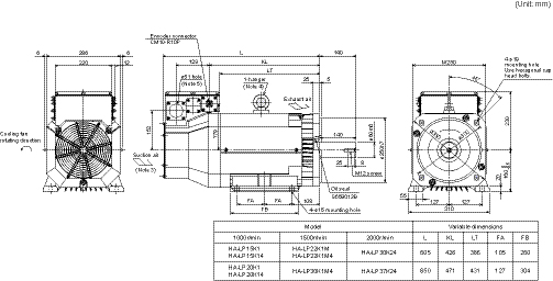
(*7)
HA-LP22K1M, HA-LP22K1M4 (*7), HA-LP30K1M4
HA-LP30K24, HA-LP37K24
* The terminal block on the terminal box housing consists of M8 screws for the motor power supply (U, V, W), and M4 screws for the cooling fan (BU, BV, BW) and for the thermal protector (OHS1, OHS2).
HA-LP25K1, HA-LP30K1, HA-LP25K14, HA-LP30K14
HA-LP37K1M, HA-LP37K1M4, HA-LP45K1M4
HA-LP45K24, HA-LP55K24
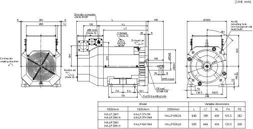
* The terminal block on the terminal box housing consists of M10 screws for the motor power supply (U, V, W), and M4 screws for the cooling fan (BU, BV, BW) and for the thermal protector (OHS1, OHS2).
Notes:
- Use a friction coupling to fasten a load.
- For dimensions where there is no tolerance listed, use general tolerance.
- Leave a clearance of at least 150mm between the motor's suction side and wall.
- When using the motor without the hanger, plug the threaded hole with a bolt of M16 X 20 or shorter.
- Make sure that oil, water and dust, etc., will not enter the motor from the lead-in hole.
- When mounting the motor with the shaft horizontal, fix the motor either with the feet or the flange, keeping the feet downward. Note that when fixing the motor with the flange, also fix the feet to support the motor.
- Contact your dealer for the delivery schedule or the compatible servo amplifier’s software version.
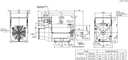
HA-LP30K1M
HA-LP30K2, HA-LP37K2
* The terminal block on the terminal box housing consists of M10 screws for the motor power supply (U, V, W), and M4 screws for the cooling fan (BU, BV, BW) and for the thermal protector (OHS1, OHS2).
HA-LP37K1, HA-LP37K14
HA-LP50K1M4
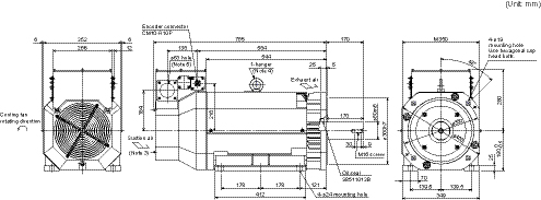
* The terminal block on the terminal box housing consists of M10 screws for the motor power supply (U, V, W), and M4 screws for the cooling fan (BU, BV, BW) and for the thermal protector (OHS1, OHS2).
Notes:
1. Use a friction coupling to fasten a load.
2. For dimensions where there is no tolerance listed, use general tolerance.
3. Leave a clearance of at least 150mm between the motor's suction side and wall.
4. When using the motor without the hanger, plug the threaded hole with a bolt of M16 X 20 or shorter.
5. Make sure that oil, water and dust, etc., will not enter the motor from the lead-in hole.
6. When mounting the motor with the shaft horizontal, fix the motor either with the feet or the flange, keeping the feet downward. Note that when fixing the motor with the flange, also fix the feet to support the motor.
Amplifier Types
|
Type |
Interface |
Control Mode |
Compatible Motor Series |
|||||||||||||||||||||||
|
Pulse Train |
Analog |
DIO |
SSCNET III |
RS-422 |
CC-Link |
EtherCAT (*4) |
Position |
Speed |
Torque |
Position Functions |
Fully Closed Loop Control |
Turret Index |
HF-KP |
HF-MP |
HF-SP |
HF-JP |
HC-LP |
HC-RP |
HC-UP |
HA-LP |
||||||
|
A-Type |
|
x |
x |
- |
- |
x |
- |
x |
x |
x |
x |
- |
- |
x |
x |
MR-J3_A |
3-Phase 200VAC |
0.05 ~ 37kW |
x |
x |
x |
x |
x |
x |
x |
x |
|
MR-J3-_A1 |
1-Phase 100VAC |
0.05 ~ 0.4kW |
x |
x |
- |
- |
- |
- |
- |
- |
||||||||||||||||
|
MR-J3-_A4 |
3-Phase 400VAC |
0.5 ~ 55kW |
- |
- |
x |
x |
- |
- |
- |
x |
||||||||||||||||
|
B Safety Type |
Advanced High-Speed Serial Bus SSCNETIII
|
- |
- |
- |
x |
- |
- |
- |
x |
x |
x |
- |
x |
- |
x |
MR-J3-_BS |
3-Phase 200VAC |
0.05 ~ 37kW |
x |
x |
x |
x |
x |
x |
x |
x |
|
MR-J3-_BS1 |
1-Phase 100VAC |
0.05 ~ 0.4kW |
x |
x |
- |
- |
- |
- |
- |
- |
||||||||||||||||
|
MR-J3-_BS4 |
3-Phase 400VAC |
0.5 ~ 55kW |
- |
- |
x |
x |
- |
- |
- |
x |
||||||||||||||||
|
B Dual Axis |
|
- |
- |
- |
x |
- |
- |
- |
x |
x |
x |
- |
- |
- |
x |
MR-J3W-_B |
3-Phase 200VAC |
0.05 ~ 0.75kW |
x |
x |
- |
- |
- |
- |
- |
- |
|
T-Type |
|
x (*2) |
- |
x (*3) |
- |
x |
x |
- |
x |
- |
- |
x |
- |
- |
x |
MR-J3-_T |
3-Phase 200VAC |
0.05 ~ 25kW |
x |
x |
x |
x |
x |
x |
x |
x |
|
MR-J3-_T1 |
1-Phase 100VAC |
0.05 ~ 0.4kW |
x |
x |
- |
- |
- |
- |
- |
- |
||||||||||||||||
|
MR-J3-_T4 |
3-Phase 400VAC |
0.5 ~ 22kW |
- |
- |
x |
x |
- |
- |
- |
x |
||||||||||||||||

Notes:
- Capacity selection software MSIZE (MRZJW3-MOTSZ111) can be downloaded for free from www.meau.com.
- Please use the manual pulse generator (MR-HDP01).
- Please use the extended IO unit (MR-J3-D01).
- Please use the interface module MR-J3-T04.
100V/200V Amplifier Selection: (Example Part No. = MR-J3-10BS)
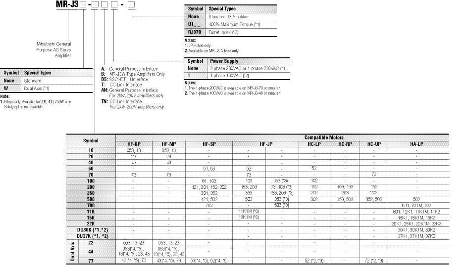
Notes:
- Converter Unit MR-J3-CR55K is required for 30kW and 37kW amplifiers.
- Available for MR-J3-A and B Safety types only.
- Use this servomotor with a dedicated servo amplifier MR-J3-_A(4)/BS(4)/T(4)-U1_ _ when increasing the maximum torque.
- These motors can be used by setting parameter No. Po04 to “_ _1_”.
- These motors are not compatible with FX3U-20SSC-H controller.
- Use a dedicated servo amplifier MR-J3-_A(4)/BS(4)/T(4)-LR/-LW for HF-JP11K1M(4) and HF-JP15K1M(4). These servomotors cannot be used with any other servo amplifiers without “-LR”.
400V Amplifier Selection: (Example Part No. = MR-J3-60A4)
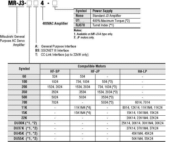
Notes:
- Converter Unit MR-J3-CR55K4 is required for 30kW to 55kW amplifiers.
- Available for the MR-J3-A and B Safety types only.
- These motors can be used by setting parameter No. Po04 to “_ _1_”.
- Use a dedicated servo amplifier MR-J3-_A(4)/BS(4)/T(4)-LR/-LW for HF-JP11K1M(4) and HF-JP15K1M(4). These servomotors cannot be used with any other servo amplifiers without “-LR”.
MR-J3-A Servo Amplifier Specifications 100/200V 22kW or Smaller
|
Servo Amplifier Model MR-J3- |
10A |
20A |
40A |
60A |
70A |
100A |
200AN |
350A |
500A |
700A |
11KA |
15KA |
22KA |
10A1 |
20A1 |
40A1 |
|
|
Stocked Item |
S |
S |
S |
S |
S |
S |
S |
S |
S |
S |
S |
S |
S |
S |
S |
S |
|
|
Main Circuit Power Supply |
Voltage/Frequency (*1, *2) |
3-phase 200 to 230VAC 50/60Hz or 1-phase 200 to 230VAC 50/60Hz (*10) |
3-phase 200 to 230VAC 50/60Hz |
1-phase 100 to 120VAC 50/60Hz |
|||||||||||||
|
Permissible Voltage Fluctuation |
For 3-phase 200 to 230VAC: 3-phase 170 to 253VAC |
3-phase 170 to 253VAC |
1-phase 85 to 132VAC |
||||||||||||||
|
Permissible Frequency Fluctuation |
±5% maximum |
||||||||||||||||
|
Control Circuit Power Supply |
Voltage/Frequency |
1-phase 200 to 230VAC 50/60Hz (*10) |
1-phase 200 to 230VAC 50/60Hz |
1-phase 100 to 120VAC 50/60Hz |
|||||||||||||
|
Permissible Voltage Fluctuation |
1-phase 170 to 253VAC |
1-phase 85 to 132VAC |
|||||||||||||||
|
Permissible Frequency Fluctuation |
±5% maximum |
||||||||||||||||
|
Power Consumption (W) |
30 |
45 |
30 |
||||||||||||||
|
Interface Power Supply |
24VDC ±10% (required current capacity: 300mA (*7)) |
||||||||||||||||
|
Regenerative Resistor/ Tolerable Regenerative Power (W) (*3, *4) |
Built-in Regenerative Resistor |
- |
10 |
10 |
10 |
20 |
20 |
100 |
100 |
130 |
170 |
- |
- |
- |
- |
10 |
10 |
|
External Regenerative Resistor (Standard Accessory) (*5, *6) |
- |
- |
- |
- |
- |
- |
- |
- |
- |
- |
500 (800) |
850 (1300) |
850 (1300) |
- |
- |
- |
|
|
Control System |
Sine-wave PWM control/current control system |
||||||||||||||||
|
Dynamic Brake |
Built-in (*8, *13) |
External option |
Built-in (*8, *13) |
||||||||||||||
|
Safety Features |
Overcurrent shutdown, regeneration overvoltage shutdown, overload shutdown (electronic thermal), servomotor overheat protection, encoder fault protection, regeneration fault protection, undervoltage/sudden power outage protection, overspeed protection, excess error protection |
||||||||||||||||
|
Position Control Mode |
Maximum Input Pulse Frequency |
1Mpps (when using differential receiver), 200kpps (when using open collector), (4Mpps (*11)) |
|||||||||||||||
|
Positioning Feedback Pulse |
Resolution per encoder/servomotor rotation: 262144 p/rev |
||||||||||||||||
|
Command Pulse Multiple |
Electronic gear A/B multiple, A: 1 to 1048576, B: 1 to 1048576, 1/10 < A/B < 2000 |
||||||||||||||||
|
Positioning Complete Width Setting |
0 to ±10000 pulses (command pulse unit) |
||||||||||||||||
|
Excess Error |
±3 rotations |
||||||||||||||||
|
Torque Limit |
Set by parameters or external analog input (0 to +10VDC/maximum torque) |
||||||||||||||||
|
Speed Control Mode |
Speed Control Range |
Analog speed command 1:2000, internal speed command 1:5000 |
|||||||||||||||
|
Analog Speed Command Input |
0 to ±10VDC/rated speed (possible to change the speed in 10V using the parameter No. PC12.) (*12) |
||||||||||||||||
|
Speed Fluctuation Rate |
±0.01% maximum (load fluctuation 0 to 100%) 0% (power fluctuation ±10%) ±0.2% maximum (ambient temperature 25°C±10°C (59°F to 95°F)), when using analog speed command |
||||||||||||||||
|
Torque Limit |
Set by parameters or external analog input (0 to +10VDC/maximum torque) (*12) |
||||||||||||||||
|
Torque Control Mode |
Analog Torque Command Input |
0 to ±8VDC/maximum torque (input impedance 10 to 12kΩ) (*12) |
|||||||||||||||
|
Speed Limit |
Set by parameters or external analog input (0 to ±10VDC/rated speed) |
||||||||||||||||
|
Structure |
Self-cooling open (IP00) |
Fan cooling open (IP00) |
Self-cooling open (IP00) |
||||||||||||||
|
Environment |
Ambient Temperature (*6, *9) |
0 to 55°C (32 to 131°F) (non-freezing), storage: -20 to 65°C (-4 to 149°F) (non-freezing) |
|||||||||||||||
|
Ambient Humidity |
90% RH maximum (non-condensing), storage: 90% RH maximum (non-condensing) |
||||||||||||||||
|
Atmosphere |
Indoors (no direct sunlight); no corrosive gas, inflammable gas, oil mist or dust |
||||||||||||||||
|
Elevation |
1000m or less above sea level |
||||||||||||||||
|
Vibration |
5.9m/s² maximum |
||||||||||||||||
|
Weight kg (lb) |
0.8 (1.8) |
0.8 (1.8) |
1.0 (2.2) |
1.0 (2.2) |
1.4 (3.1) |
1.4 (3.1) |
2.1 (4.6) |
2.3 (5.1) |
4.6 (10) |
6.2 (14) |
18 (40) |
18 (40) |
19 (42) |
0.8 (1.8) |
0.8 (1.8) |
1.0 (2.2) |
|
Notes:
- Rated output and speed of a servomotor are applicable when the servo amplifier, combined with the servomotor, is operated within the specified power supply voltage and frequency. Torque drops when the power supply voltage is below the specified value.
- For torque characteristics when combined with a servomotor, refer to the section “Servomotor torque characteristics” in this catalog.
- Optimal regenerative resistor varies for each system. Select the most suitable regenerative resistor by using the capacity selection software.
- Refer to the section “Options • Optional regeneration unit” in this catalog for the tolerable regenerative power (W).
- The servo amplifier (MR-J3-_KA-PX) without an enclosed regenerative resistor is also available.
- , (standard accessory) are used with cooling fans (2 units of 92 x 92mm, minimum air flow: 1.0m³/min). Note that change in the parameter No. PA02 is required.
- 300mA is the value when all of the input/output points are used. The current capacity can be stepped down according to the number of input/output points in use. Refer to “MR-J3-_A SERVO AMPLIFIER INSTRUCTION MANUAL” for details.
- Special specification models without a dynamic brake, MR-J3-_A -ED and MR-J3-_A1-ED, are also available for 7kW or smaller servo amplifier.
- The MR-J3-350A or smaller servo amplifier can be installed close together. In this case, keep the ambient temperature within 0 to 45°C (32 to 113°F), or use the servo amplifier with 75% or less of the effective load rate.
- The special specification model, MR-J3-_A-U004, is also available for 1-phase 200 to 240 VAC.
- 4Mpps compatible servo amplifier (MR-J3-_A(1)-KE) is also available.
- High resolution analog speed command and analog torque command is available with a set of MR-J3-_A(1)-RJ040 and the extension IO unit, MR-J3-D01.
- When using the built-in dynamic brake, refer to “MR-J3-_A SERVO AMPLIFIER INSTRUCTION MANUAL” for the permissible load inertia moment ratio.
MR-J3-A Servo Amplifier Specifications: 200VAC, 30kW or Larger
|
Drive Unit Model |
MR-J3-DU30KA |
MR-J3-DU37KA |
|
|
Stocked Item |
- |
- |
|
|
Main Circuit Power Supply |
Voltage/Frequency (*1) |
The drive unit’s main circuit power is supplied from the converter unit. |
|
|
Permissible Voltage Fluctuation |
|||
|
Permissible Frequency Fluctuation |
|||
|
Control Circuit Power Supply |
Voltage/Frequency |
1-phase 200 to 230VAC 50/60Hz |
|
|
Permissible Voltage Fluctuation |
1-phase 170 to 253VAC |
||
|
Permissible Frequency Fluctuation |
±5% maximum |
||
|
Power Consumption (W) |
45 |
||
|
Interface Power Supply |
24VDC ±10% (required current capacity: 300mA (*3)) |
||
|
Control System |
Sine-wave PWM control/current control system |
||
|
Dynamic Brake |
External option |
||
|
Safety Features |
Overcurrent shutdown, overload shutdown (electronic thermal), servomotor overheat protection, encoder fault protection, undervoltage/sudden power outage protection, overspeed protection, excess error protection |
||
|
Position Control Mode |
Maximum Input Pulse Frequency |
1Mpps (when using differential receiver), 200kpps (when using open collector) |
|
|
Positioning Feedback Pulse |
Resolution per encoder/servomotor rotation: 262144 p/rev |
||
|
Command Pulse Multiple |
Electronic gear A/B multiple, A: 1 to 1048576, B: 1 to 1048576, 1/10 < A/B < 2000 |
||
|
Positioning Complete Width Setting |
0 to ±10000 pulses (command pulse unit) |
||
|
Excess Error |
±3 rotations |
||
|
Torque Limit |
Set by parameters or external analog input (0 to +10VDC/maximum torque) |
||
|
Speed Control Mode |
Speed Control Range |
Analog speed command 1:2000, internal speed command 1:5000 |
|
|
Analog Speed Command Input |
0 to ±10VDC/rated speed (possible to change the speed in 10V using the parameter No. PC12.) |
||
|
Speed Fluctuation Rate |
±0.01% maximum (load fluctuation 0 to 100%) 0% (power fluctuation ±10%) ±0.2% maximum (ambient temperature 25°C±10°C (59°F to 95°F)), when using analog speed command |
||
|
Torque Limit |
Set by parameters or external analog input (0 to +10VDC/maximum torque) |
||
|
Torque Control Mode (*2) |
Analog Torque Command Input |
0 to ±8VDC/maximum torque (input impedance 10 to 12kΩ) |
|
|
Speed Limit |
Set by parameters or external analog input (0 to ±10VDC/rated speed) |
||
|
Structure |
Fan cooling open (IP00) |
||
|
Weight kg (lb) |
26 (57) |
||
|
Environment |
Ambient Temperature |
0 to 55°C (32 to 131°F) (non-freezing), storage: -20 to 65°C (-4 to 149°F) (non-freezing) |
|
|
Ambient Humidity |
90% RH maximum (non-condensing), storage: 90% RH maximum (non-condensing) |
||
|
Atmosphere |
Indoors (no direct sunlight); no corrosive gas, inflammable gas, oil mist or dust |
||
|
Elevation |
1000m or less above sea level |
||
|
Vibration |
5.9m/s² maximum |
||
Notes:
- Rated output and speed of a servomotor are applicable when the drive unit and the converter unit, combined with the servomotor, are operated within the specified power supply voltage and frequency.
Torque drops when the power supply voltage is below the specified value. - For torque characteristics when combined with a servomotor, refer to the section “Servomotor torque characteristics” in this catalog.
- The interface power supply can be shared with the drive unit and the converter unit. When all of the input/output points are used, 300mA is required for the drive unit, and 130mA is required for the converter unit. The current capacity can be stepped down according to the number of input/output points in use. Refer to “MR-J3-_A SERVO AMPLIFIER INSTRUCTION MANUAL” for details.
MR-J3-A Servo Amplifier Specifications, 400VAC, 22kW or Smaller
|
Servo Amplifier Model MR-J3- |
60A4 |
100A4 |
200A4 |
350A4 |
500A4 |
700A4 |
11KA4 |
15KA4 |
22KA4 |
|
|
Stocked Item |
S |
S |
S |
S |
S |
S |
S |
S |
S |
|
|
Main Circuit Power Supply |
Voltage/Frequency (*1, *2) |
3-phase 380 to 480VAC 50/60Hz |
||||||||
|
Permissible Voltage Fluctuation |
3-phase 323 to 528VAC |
|||||||||
|
Permissible Frequency Fluctuation |
±5% maximum |
|||||||||
|
Control Circuit Power Supply |
Voltage/Frequency |
1-phase 380 to 480VAC 50/60Hz |
||||||||
|
Permissible Voltage Fluctuation |
1-phase 323 to 528VAC |
|||||||||
|
Permissible Frequency Fluctuation |
±5% maximum |
|||||||||
|
Power Consumption (W) |
30 |
45 |
||||||||
|
Interface Power Supply |
24VDC ±10% (required current capacity: 300mA (*7)) |
|||||||||
|
Regenerative Resistor/ Tolerable Regenerative Power (W) (*3, *4) |
Built-in Regenerative Resistor |
15 |
15 |
100 |
100 |
130 (*9) |
170 (*9) |
- |
- |
- |
|
External Regenerative Resistor (Standard Accessory) (*5, *6) |
- |
- |
- |
- |
- |
- |
500 (800) |
850 (1300) |
850 (1300) |
|
|
Control System |
Sine-wave PWM control/current control system |
|||||||||
|
Dynamic Brake |
Built-in (*8, *10) |
External option |
||||||||
|
Safety Features |
Overcurrent shutdown, regeneration overvoltage shutdown, overload shutdown (electronic thermal), servomotor |
|||||||||
|
Position Control Mode |
Maximum Input Pulse Frequency |
1Mpps (when using differential receiver), 200kpps (when using open collector) |
||||||||
|
Positioning Feedback Pulse |
Resolution per encoder/servomotor rotation: 262144 p/rev |
|||||||||
|
Command Pulse Multiple |
Electronic gear A/B multiple, A: 1 to 1048576, B: 1 to 1048576, 1/10 < A/B < 2000 |
|||||||||
|
Positioning Complete Width Setting |
0 to ±10000 pulses (command pulse unit) |
|||||||||
|
Excess Error |
±3 rotations |
|||||||||
|
Torque Limit |
Set by parameters or external analog input (0 to +10VDC/maximum torque) |
|||||||||
|
Speed Control Mode |
Speed Control Range |
Analog speed command 1:2000, internal speed command 1:5000 |
||||||||
|
Analog Speed Command Input |
0 to ±10VDC/rated speed (possible to change the speed in 10V using the parameter No. PC12.) (*11) |
|||||||||
|
Speed Fluctuation Rate |
±0.01% maximum (load fluctuation 0 to 100%) 0% (power fluctuation ±10%) ±0.2% maximum (ambient temperature 25°C±10°C (59°F to 95°F)), when using analog speed command |
|||||||||
|
Torque Limit |
Set by parameters or external analog input (0 to +10VDC/maximum torque) (*11) |
|||||||||
|
Torque Control Mode |
Analog Torque Command Input |
0 to ±8VDC/maximum torque (input impedance 10 to 12kΩ) (*11) |
||||||||
|
Speed Limit |
Set by parameters or external analog input (0 to ±10VDC/rated speed) |
|||||||||
|
Structure |
Self-cooling open (IP00) |
Fan cooling open (IP00) |
||||||||
|
Environment |
Ambient Temperature (*6) |
0 to 55°C (32 to 131°F) (non-freezing), storage: -20 to 65°C (-4 to 149°F) (non-freezing) |
||||||||
|
Ambient Humidity |
90% RH maximum (non-condensing), storage: 90% RH maximum (non-condensing) |
|||||||||
|
Atmosphere |
Indoors (no direct sunlight); no corrosive gas, inflammable gas, oil mist or dust |
|||||||||
|
Elevation |
1000m or less above sea level |
|||||||||
|
Vibration |
5.9m/s² maximum |
|||||||||
|
Weight kg (lb) |
1.7 (3.7) |
1.7 (3.7) |
2.1 (4.6) |
4.6 (10) |
4.6 (10) |
6.2 (14) |
18 (40) |
18 (40) |
19 (42) |
|
Notes:
- Rated output and speed of a servomotor are applicable when the servo amplifier, combined with the servomotor, is operated within the specified power supply voltage and frequency. Torque drops when the power supply voltage is below the specified value.
- For torque characteristics when combined with a servomotor, refer to the section “Servomotor torque characteristics” in this catalog.
- Optimal regenerative resistor varies for each system. Select the most suitable regenerative resistor by using the capacity selection software.
- Refer to the section “Options • Optional regeneration unit” in this catalog for the tolerable regenerative power (W).
- The servo amplifier (MR-J3-_KA4-PX) without an enclosed regenerative resistor is also available.
- The value in ( ) applies when the external regenerative resistors, GRZG400-_Ω, (standard accessory) are used with cooling fans (2 units of 92 x 92mm, minimum air flow: 1.0m³/min). Note that change in the parameter No. PA02 is required.
- 300mA is the value when all of the input/output points are used. The current capacity can be stepped down according to the number of input/output points in use. Refer to “MR-J3-_A SERVO AMPLIFIER INSTRUCTION MANUAL” for details.
- Special specification models without a dynamic brake, MR-J3-_A4 -ED, are also available for 7kW or smaller servo amplifier.
- The amplifier built-in resistor is compatible with the maximum torque deceleration when the motor is used within the rated speed and the recommended load/motor inertia moment ratio. Contact Mitsubishi if the operating motor speed and the load/motor inertia moment ratio exceed the rated speed and the recommended ratio.
- When using the built-in dynamic brake, refer to “MR-J3-_A SERVO AMPLIFIER INSTRUCTION MANUAL” for the permissible load inertia moment ratio.
- For the servo amplifier 11kW to 22kW, high resolution analog speed command and analog torque command is available with a set of MR-J3-_A4-RJ040 and the extension IO unit, MR-J3-D01. Servo amplifier 7kW or smaller, compatible with high resolution analog speed torque command, will be available.
MR-J3-A Servo Amplifier Specifications, 400VAC, 30kW or Larger
|
Drive Unit Model |
MR-J3-DU30KA4 |
MR-J3-DU37KA4 |
MR-J3-DU45KA4 |
MR-J3-55KA4 |
|
|
Stocked Item |
- |
||||
|
Main Circuit Power Supply |
Voltage/Frequency (*1) |
The drive unit’s main circuit power is supplied from the converter unit. |
|||
|
Permissible Voltage Fluctuation |
|||||
|
Permissible Frequency Fluctuation |
|||||
|
Control Circuit Power Supply |
Voltage/Frequency |
1-phase 380 to 480VAC 50/60Hz |
|||
|
Permissible Voltage Fluctuation |
1-phase 323 to 528VAC |
||||
|
Permissible Frequency Fluctuation |
±5% maximum |
||||
|
Power Consumption (W) |
45 |
||||
|
Interface Power Supply |
24VDC ±10% (required current capacity: 300mA (*3)) |
||||
|
Control System |
Sine-wave PWM control/current control system |
||||
|
Dynamic Brake |
External option |
||||
|
Safety Features |
Overcurrent shutdown, overload shutdown (electronic thermal), servomotor overheat protection, encoder fault protection, undervoltage/sudden power outage protection, overspeed protection, excess error protection |
||||
|
Position Control Mode |
Maximum Input Pulse Frequency |
1Mpps (when using differential receiver), 200kpps (when using open collector) |
|||
|
Positioning Feedback Pulse |
Resolution per encoder/servomotor rotation: 262144 p/rev |
||||
|
Command Pulse Multiple |
Electronic gear A/B multiple, A: 1 to 1048576, B: 1 to 1048576, 1/10 < A/B < 2000 |
||||
|
Positioning Complete Width Setting |
0 to ±10000 pulses (command pulse unit) |
||||
|
Excess Error |
±3 rotations |
||||
|
Torque Limit |
Set by parameters or external analog input (0 to +10VDC/maximum torque) |
||||
|
Speed Control Mode |
Speed Control Range |
Analog speed command 1:2000, internal speed command 1:5000 |
|||
|
Analog Speed Command Input |
0 to ±10VDC/rated speed (possible to change the speed in 10V using the parameter No. PC12.) |
||||
|
Speed Fluctuation Rate |
±0.01% maximum (load fluctuation 0 to 100%) 0% (power fluctuation ±10%) ±0.2% maximum |
||||
|
Torque Limit |
Set by parameters or external analog input (0 to +10VDC/maximum torque) |
||||
|
Torque Control Mode (*2) |
Analog Torque Command Input |
0 to ±8VDC/maximum torque (input impedance 10 to 12kΩ) |
|||
|
Speed Limit |
Set by parameters or external analog input (0 to ±10VDC/rated speed) |
||||
|
Structure |
Fan cooling open (IP00) |
||||
|
Weight kg (lb) |
18 (40) |
26 (57) |
|||
|
Environment |
Ambient Temperature |
0 to 55°C (32 to 131°F) (non-freezing), storage: -20 to 65°C (-4 to 149°F) (non-freezing) |
|||
|
Ambient Humidity |
90% RH maximum (non-condensing), storage: 90% RH maximum (non-condensing) |
||||
|
Atmosphere |
Indoors (no direct sunlight); no corrosive gas, inflammable gas, oil mist or dust |
||||
|
Elevation |
1000m or less above sea level |
||||
|
Vibration |
5.9m/s2 maximum |
||||
Notes:
- Rated output and speed of a servomotor are applicable when the drive unit and the converter unit, combined with the servomotor, are operated within the specified power supply voltage and frequency. Torque drops when the power supply voltage is below the specified value.
- For torque characteristics when combined with a servomotor, refer to the section “Servomotor torque characteristics” in this catalog.
- The interface power supply can be shared with the drive unit and the converter unit. When all of the input/output points are used, 300mA is required for the drive unit, and 130mA is required for the converter unit. The current capacity can be stepped down according to the number of input/output points in use. Refer to “MR-J3-_A SERVO AMPLIFIER INSTRUCTION MANUAL” for details.
MR-J3-A-RJ070 Servo Amplifier Specifications 200VAC, 22kW or Smaller (Indexer)
|
Servo Amplifier Model MR-J3-_-RJ070 |
10A |
20A |
40A |
60A |
70A |
100A |
200AN |
350A |
500A |
700A |
11KA |
15KA |
22KA |
10A1 |
20A1 |
40A1 |
|
|
Stocked Item |
S |
S |
S |
S |
S |
- |
S |
S |
S |
S |
- |
- |
- |
- |
- |
- |
|
|
Main Circuit Power Supply |
Voltage/Frequency |
3-phase 200 to 230VAC 50/60Hz or 1-phase 200 to 230VAC 50/60Hz |
3-phase 200 to 230VAC 50/60Hz |
1-phase 100 to 120VAC 50/60Hz |
|||||||||||||
|
Permissible Voltage Fluctuation |
For 1-phase 230VAC: 207 to 253VAC |
1-phase 170 to 253VAC |
1-phase 85 to 132VAC |
||||||||||||||
|
Permissible Frequency Fluctuation |
±5% maximum |
||||||||||||||||
|
Control Circuit Power Supply |
Voltage/Frequency |
1-phase 200 to 230VAC 50/60Hz |
1-phase 100 to 120VAC 50/60Hz |
||||||||||||||
|
Permissible Voltage Fluctuation |
1-phase 170 to 253VAC |
1-phase 85 to 132VAC |
|||||||||||||||
|
Permissible Frequency Fluctuation |
±5% maximum |
||||||||||||||||
|
Power Consumption (W) |
30 |
45 |
30 |
||||||||||||||
|
Inrush Current |
Refer to MR-J3-_A Servo Amplifier Instruction Manual |
||||||||||||||||
|
Interface Power Supply |
24VDC ±10% (300mA) (*1) |
||||||||||||||||
|
Control System |
Sine-wave PWM control/current control system |
||||||||||||||||
|
Dynamic Brake |
Built-in |
External option |
Built-in |
||||||||||||||
|
Safety Features |
Overcurrent shutdown, regeneration overvoltage shutdown, overload shutdown (electronic thermal), servomotor overheat protection, encoder fault protection, regeneration fault protection, undervoltage/sudden power outage protection, overspeed protection, excess error protection |
||||||||||||||||
|
Indexer Positioning (Turret) |
Max. No. of Stations |
MR-J3-_A-RJ070 only: 15 stations, With MR-J3-D01: 255 stations |
|||||||||||||||
|
Number of Gears on Servomotor / Machine (Electronic Gears) |
1/9999<MCX/CDV<9999, CDVx STN<32767, CMX x CDV<100000 |
||||||||||||||||
|
In-Position Range Setting |
0 to ±10000 pulses (command pulse unit) |
||||||||||||||||
|
Error Excessive |
±3 rotations |
||||||||||||||||
|
Torque Limit |
Set by parameters or external analog input (0 to +10VDC/maximum torque) |
||||||||||||||||
|
Structure |
Self-cooling open (IP00) |
Forced-cooling open (IP00) |
Self-cooling open (IP00) |
||||||||||||||
|
Environment |
Ambient Temperature |
0 to 55°C (32 to 131°F) (non-freezing), storage: -20 to 65°C (-4 to 149°F) (non-freezing) (*2) |
|||||||||||||||
|
Ambient Humidity |
90% RH maximum (non-condensing), storage: 90% RH maximum (non-condensing) |
||||||||||||||||
|
Atmosphere |
Indoors (no direct sunlight); no corrosive gas, inflammable gas, oil mist or dust |
||||||||||||||||
|
Elevation |
1000m or less above sea level |
||||||||||||||||
|
Vibration |
5.9m/s² maximum |
||||||||||||||||
|
Weight kg (lb) |
0.8 (1.8) |
0.8 (1.8) |
1.0 (2.2) |
1.0 (2.2) |
1.4 (3.1) |
1.4 (3.1) |
2.1 (4.6) |
2.3 (5.1) |
4.6 (10) |
6.2 (14) |
18 (40) |
18 (40) |
19 (42) |
0.8 (1.8) |
0.8 (1.8) |
1.0 (2.2) |
|
Notes:
- 300mA is the value when all I/O signals are used. The current capacity can be decreased by reducing the number of I/O points.
- When closely mounting the servo amplifiers of 3.5kW or less, operate them at the ambient temperatures of 0 to 45°C or at 75% or smaller effective ratio loads.
MR-J3-A-RJ070 Servo Amplifier Specifications 400VAC, 22kW or Smaller (Indexer)
|
Servo Amplifier Model MR-J3-_-RJ070 |
60A4 |
100A4 |
200A4 |
350A4 |
500A4 |
700A4 |
11KA4 |
15KA4 |
22KA4 |
|
|
Stocked Item |
- |
|||||||||
|
Main Circuit Power Supply |
Voltage/Frequency |
3-phase 380 to 480VAC 50/60Hz |
||||||||
|
Permissible Voltage Fluctuation |
3-phase 323 to 528VAC |
|||||||||
|
Permissible Frequency Fluctuation |
±5% maximum |
|||||||||
|
Power Supply Equipment Capacity |
Refer to MR-J3-_A Servo Amplifier Instruction Manual |
|||||||||
|
Inrush Current |
Refer to MR-J3-_A Servo Amplifier Instruction Manual |
|||||||||
|
Control Circuit Power Supply |
Voltage/Frequency |
1-phase 380 to 480VAC 50/60Hz |
||||||||
|
Permissible Voltage Fluctuation |
1-phase 323 to 528VAC |
|||||||||
|
Permissible Frequency Fluctuation |
±5% maximum |
|||||||||
|
Power Consumption (W) |
30 |
45 |
||||||||
|
Inrush Current |
Refer to MR-J3-_A Servo Amplifier Instruction Manual |
|||||||||
|
Interface Power Supply |
24VDC ±10% (300mA) (*1) |
|||||||||
|
Control System |
Sine-wave PWM control/current control system |
|||||||||
|
Dynamic Brake |
Built-in |
External option |
||||||||
|
Safety Features |
Overcurrent shutdown, regeneration overvoltage shutdown, overload shutdown (electronic thermal), servomotor overheat protection, encoder fault protection, regeneration fault protection, undervoltage/sudden power outage protection, overspeed protection, excess error protection |
|||||||||
|
Indexer Positioning (Turret) |
Maximum Number of Stations |
RJ070 only: 15 stations, With MR-J3-D01: 255 stations |
||||||||
|
Number of Gears on Servomotor/ Machine (Electronic Gears) |
1/9999<MCX/CDV<9999, CDV x STN<32767, CMX x CDV<100000 |
|||||||||
|
In-Position Range Setting |
0 to ±10000 pulses (command pulse unit) |
|||||||||
|
Error Excessive |
±3 rotations |
|||||||||
|
Torque Limit |
Set by parameters or external analog input (0 to +10VDC/maximum torque) |
|||||||||
|
Structure |
Self-cooling open (IP00) |
Forced cooling open (IP00) |
||||||||
|
Environment |
Ambient Temperature |
0 to 55°C (32 to 131°F) (non-freezing), storage: -20 to 65°C (-4 to 149°F) (non-freezing) |
||||||||
|
Ambient Humidity |
90% RH maximum (non-condensing), storage: 90% RH maximum (non-condensing) |
|||||||||
|
Atmosphere |
Indoors (no direct sunlight); no corrosive gas, inflammable gas, oil mist or dust |
|||||||||
|
Elevation |
1000m or less above sea level |
|||||||||
|
Vibration |
5.9m/s² maximum |
|||||||||
|
Weight kg (lb) |
1.7 (3.7) |
1.7 (3.7) |
2.1 (4.6) |
4.6 (10) |
4.6 (10) |
6.2 (14) |
18 (40) |
18 (40) |
19 (42) |
|
Note: 1. 300mA is the value when all I/O signals are used. The current capacity can be decreased by reducing the number of I/O points.
MR-J3-B Safety Servo Amplifier Specifications 100V/200VAC, 22kW or Smaller
|
Servo Amplifier Model MR-J3- |
10BS |
20BS |
40BS |
60BS |
70BS |
100BS |
200BS |
350BS |
500BS |
700BS |
11KBS |
15KBS |
22KBS |
10BS1 |
20BS1 |
40BS1 |
|
|
Stocked Item |
S |
S |
S |
S |
S |
S |
S |
S |
S |
S |
S |
S |
S |
S |
S |
S |
|
|
Main Circuit Power Supply |
Voltage/Frequency (*1, *2) |
3-phase 200 to 230VAC 50/60Hz or 1-phase 200 to 230VAC 50/60Hz (*10) |
3-phase 200 to 230VAC 50/60Hz |
1-phase 100 to 120VAC 50/60Hz |
|||||||||||||
|
Permissible Voltage Fluctuation |
For 3-phase 200 to 230VAC: 3-phase 170 to 253VAC |
3-phase 170 to 253VAC |
1-phase 85 to 132VAC |
||||||||||||||
|
Permissible Frequency Fluctuation |
±5% maximum |
||||||||||||||||
|
Control Circuit Power Supply |
Voltage/Frequency |
1-phase 200 to 230VAC 50/60Hz (*10) |
1-phase 200 to 230VAC 50/60Hz |
1-phase 100 to 120VAC 50/60Hz |
|||||||||||||
|
Permissible Voltage Fluctuation |
1-phase 170 to 253VAC |
1-phase 85 to 132VAC |
|||||||||||||||
|
Permissible Frequency Fluctuation |
±5% maximum |
||||||||||||||||
|
Power Consumption (W) |
30 |
45 |
30 |
||||||||||||||
|
Interface Power Supply |
24VDC ±10% (required current capacity: 150mA (*7)) |
||||||||||||||||
|
Regenerative Resistor/ Tolerable Regenerative Power (W) (*3, *4) |
Built-in Regenerative Resistor |
- |
10 |
10 |
10 |
20 |
20 |
100 |
100 |
130 |
170 |
- |
- |
- |
- |
10 |
10 |
|
External Regenerative Resistor (Standard Accessory) (*5, *6) |
- |
- |
- |
- |
- |
- |
- |
- |
- |
- |
500 (800) |
850 (1300) |
850 (1300) |
- |
- |
- |
|
|
Control System |
Sine-wave PWM Control/Current Control System |
||||||||||||||||
|
Dynamic Brake |
Built-in (*8, *11) |
External option |
Built-in (*8, *11) |
||||||||||||||
|
Safety Features |
Overcurrent shutdown, regeneration overvoltage shutdown, overload shutdown (electronic thermal), servomotor overheat protection, encoder fault protection, regeneration fault protection, undervoltage/sudden power outage protection, overspeed protection, excess error protection |
||||||||||||||||
|
Structure |
Self-Cooling Open |
Self-cooling open (IP00) |
Fan cooling open (IP00) |
Self-cooling open (IP00) |
|||||||||||||
|
Environment |
Ambient Temp. (*9) |
0 to 55°C (32 to 131°F) (non-freezing), storage: -20 to 65°C (-4 to 149°F) (non-freezing) |
|||||||||||||||
|
Ambient Humidity |
90% RH maximum (non-condensing), storage: 90% RH maximum (non-condensing) |
||||||||||||||||
|
Atmosphere |
Indoors (no direct sunlight); no corrosive gas, inflammable gas, oil mist or dust |
||||||||||||||||
|
Elevation |
1000m or less above sea level |
||||||||||||||||
|
Vibration |
5.9m/s² maximum |
||||||||||||||||
|
Weight kg (lb) |
0.8 (1.8) |
0.8 (1.8) |
1.0 (2.2) |
1.0 (2.2) |
1.4 (3.1) |
1.4 (3.1) |
2.1 (4.6) |
2.3 (5.1) |
4.6 (10) |
6.2 (14) |
18 (40) |
18 (40) |
19 (42) |
0.8 (1.8) |
0.8 (1.8) |
1.0 (2.2) |
|
Notes:
- Rated output and rated speed of the servomotor used in combination with the servo amplifier are as indicated when using the power supply voltage and frequency listed. The torque drops when the power supply voltage is less than specified.
- For torque characteristics when combined with a servomotor, refer to the section “Servomotor torque characteristics” in the MR-J3 manual.
- Optimal regenerative resistor varies for each system. Select the most suitable regenerative resistor by using the capacity selection software.
- Refer to the section “Options • Optional regeneration unit” in the MR-J3 manual for the tolerable regenerative power (W).
- The servo amplifier (MR-J3-_KB-PX) without an enclosed regenerative resistor is also available.
- The value in ( ) applies when the external regenerative resistors, GRZG400-_Ω, (standard accessory) are used with cooling fans (2 units of 92 x 92mm, minimum air flow: 1.0m³/min). Note that change in the parameter No. PA02 is required.
- 150mA is the value when all of the input/output points are used. The current capacity can be stepped down according to the number of input/output points in use. Refer to “MR-J3-_B Safety SERVO AMPLIFIER INSTRUCTION MANUAL” for details.
- Special specification models without a dynamic brake, MR-J3-_BS-ED and MR-J3-_B1-ED, are also available.
- The MR-J3-350BS or smaller servo amplifier can be installed closely. In this case, keep the ambient temperature within 0 to 45°C (32 to 113°F), or use the servo amplifier with 75% or less of the effective load rate.
- The special specification model, MR-J3-_BS-U004, is also available for 1-phase 200 to 240VAC.
- When using the built-in dynamic brake, refer to MR-J3-_B Safety SERVO AMPLIFIER INSTRUCTION MANUAL for the permissible load inertia moment ratio.
MR-J3-B Safety Servo Amplifier Specifications: 200VAC, 30kW or Larger
|
Drive Unit Model |
MR-J3-DU30KBS |
MR-J3-DU37KBS |
|
|
Stocked Item |
- |
||
|
Main Circuit Power Supply |
Voltage/Frequency (*1) |
The drive unit’s main circuit power is supplied from the converter unit |
|
|
Permissible Voltage Fluctuation |
|||
|
Permissible Frequency Fluctuation |
|||
|
Control Circuit Power Supply |
Voltage/Frequency |
1-phase 200 to 230VAC 50/60Hz |
|
|
Permissible Voltage Fluctuation |
1-phase 170 to 253VAC |
||
|
Permissible Frequency Fluctuation |
±5% maximum |
||
|
Power Consumption (W) |
45 |
||
|
Interface Power Supply |
24VDC ±10% (required current capacity: 150mA (*2)) |
||
|
Control System |
Sine-wave PWM control/current control system |
||
|
Dynamic Brake |
External option |
||
|
Safety Features |
Overcurrent shutdown, overload shutdown (electronic thermal), servomotor overheat protection, encoder fault protection, undervoltage/sudden power outage protection, overspeed protection, excess error protection |
||
|
Structure |
Fan cooling open (IP00) |
||
|
Weight kg (lb) |
26 (57) |
||
|
Environment |
Ambient Temperature |
0 to 55°C (32 to 131°F) (non-freezing), storage: -20 to 65°C (-4 to 149°F) (non-freezing) |
|
|
Ambient Humidity |
90% RH maximum (non-condensing), storage: 90% RH maximum (non-condensing) |
||
|
Atmosphere |
Indoors (no direct sunlight); no corrosive gas, inflammable gas, oil mist or dust |
||
|
Elevation |
1000m or less above sea level |
||
|
Vibration |
5.9m/s² maximum |
||
Notes:
- Rated output and rated speed of the servomotor used in combination with the drive unit and the converter unit are as indicated when using the power supply voltage and frequency listed. The torque drops when the power supply voltage is less than specified.
- The interface power supply can be shared with the drive unit and the converter unit. When all of the input/output points are used, 150mA is required for the drive unit, and 130mA is required for the converter unit. The current capacity can be stepped down according to the number of input/output points in use. Refer to “MR-J3-_B Safety SERVO AMPLIFIER INSTRUCTION MANUAL” for details.
MR-J3-B Safety Servo Amplifier Specifications: 400VAC, 22kW or Smaller
|
Servo Amplifier Model MR-J3- |
60BS4 |
100BS4 |
200BS4 |
350BS4 |
500BS4 |
700BS4 |
11KBS4 |
15KBS4 |
22KBS4 |
|
|
Stocked Item |
S |
S |
S |
S |
S |
S |
S |
S |
S |
|
|
Main Circuit Power Supply |
Voltage/Frequency (*1, *2) |
3-phase 380 to 480VAC 50/60Hz |
||||||||
|
Permissible Voltage Fluctuation |
3-phase 323 to 528VAC |
|||||||||
|
Permissible Frequency Fluctuation |
±5% maximum |
|||||||||
|
Control Circuit Power Supply |
Voltage/Frequency |
1-phase 380 to 480VAC 50/60Hz |
||||||||
|
Permissible Voltage Fluctuation |
1-phase 323 to 528VAC |
|||||||||
|
Permissible Frequency Fluctuation |
±5% maximum |
|||||||||
|
Power Consumption (W) |
30 |
45 |
||||||||
|
Interface Power Supply |
24VDC ±10% (required current capacity: 150mA (*7)) |
|||||||||
|
Regenerative Resistor/ Tolerable Regenerative Power (W) |
Built-In Regenerative Resistor |
15 |
15 |
100 |
100 |
130 (*9) |
170 (*9) |
- |
- |
- |
|
External Regenerative Resistor (Standard Accessory) (*5, *6) |
- |
- |
- |
- |
- |
- |
500 (800) |
850 (1300) |
850 (1300) |
|
|
Control System |
Sine-wave PWM control/current control system |
|||||||||
|
Dynamic Brake |
Built-in (*8, 10) |
External option |
||||||||
|
Safety Features |
Overcurrent shutdown, regeneration overvoltage shutdown, overload shutdown (electronic thermal), servomotor overheat protection, encoder fault protection, regeneration fault protection, undervoltage/sudden power outage protection, overspeed protection, excess error protection |
|||||||||
|
Structure |
Self-cooling open (IP00) |
Fan cooling open (IP00) |
||||||||
|
Environment |
Ambient Temperature |
0 to 55°C (32 to 131°F) (non-freezing), storage: -20 to 65°C (-4 to 149°F) (non-freezing) |
||||||||
|
Ambient Humidity |
90% RH maximum (non-condensing), storage: 90% RH maximum (non-condensing) |
|||||||||
|
Atmosphere |
Indoors (no direct sunlight); no corrosive gas, inflammable gas, oil mist or dust |
|||||||||
|
Elevation |
1000m or less above sea level |
|||||||||
|
Vibration |
5.9m/s2 maximum |
|||||||||
|
Weight kg (lb) |
1.7 (3.7) |
1.7 (3.7) |
2.1 (4.6) |
4.6 (10) |
4.6 (10) |
6.2 (14) |
18 (40) |
18 (40) |
19 (42) |
|
Notes:
- Rated output and rated speed of the servomotor used in combination with the servo amplifier are as indicated when using the power supply voltage and frequency listed. The torque drops when the power supply voltage is less than specified.
- For torque characteristics when combined with a servomotor, refer to the section “Servomotor torque characteristics” in the MR-J3 manual.
- Optimal regenerative resistor varies for each system. Select the most suitable regenerative resistor by using the capacity selection software.
- Refer to the section “Options • Optional regeneration unit” in the MR-J3 manual for the tolerable regenerative power (W).
- The servo amplifier (MR-J3-_KB4-PX) without an enclosed regenerative resistor is also available.
- The value in ( ) applies when the external regenerative resistors, GRZG400-_Ω, (standard accessory) are used with cooling fans (2 units of 92 X 92mm, minimum air flow: 1.0m³/min). Note that change in the parameter No. PA02 is required.
- 150mA is the value when all of the input/output points are used. The current capacity can be stepped down according to the number of input/output points in use. Refer to “MR-J3-_B SAFETY SERVO AMPLIFIER INSTRUCTION MANUAL” for details.
- Special specification models without a dynamic brake, MR-J3-_B4-ED, are also available.
- The amplifier built-in resistor is compatible with the maximum torque deceleration when the motor is used within the rated speed and the recommended load/motor inertia moment ratio. Contact Mitsubishi if the operating motor speed and the load/motor inertia moment ratio exceed the rated speed and the recommended ratio.
- For the servo amplifier 5kW or 7kW, the load/motor of inertia moment ratio must be 5 times or less when the amplifier built-in dynamic brake is used, and the motor speed exceeds 2000r/min.
MR-J3-B Safety Servo Amplifier Specifications: 400VAC, 30kW or Larger
|
Drive Unit Model |
MR-J3-DU30KBS4 |
MR-J3-DU37KBS4 |
MR-J3-DU45KBS4 |
MR-J3-DU55KBS4 |
|
|
Stocked Item |
- |
||||
|
Main Circuit Power Supply |
Voltage/Frequency (*1) |
The drive unit’s main circuit power is supplied from the converter unit. |
|||
|
Permissible Voltage Fluctuation |
|||||
|
Permissible Frequency Fluctuation |
|||||
|
Control Circuit Power Supply |
Voltage/Frequency |
1-phase 380 to 480VAC 50/60Hz |
|||
|
Permissible Voltage Fluctuation |
1-phase 323 to 528VAC |
||||
|
Permissible Frequency Fluctuation |
±5% maximum |
||||
|
Power Consumption (W) |
45 |
||||
|
Interface Power Supply |
24VDC ±10% (required current capacity: 150mA (*2)) |
||||
|
Control System |
Sine-wave PWM control/current control system |
||||
|
Dynamic Brake |
External option |
||||
|
Safety Features |
Overcurrent shutdown, overload shutdown (electronic thermal), servomotor overheat protection, encoder fault protection, undervoltage/sudden power outage protection, overspeed protection, excess error protection |
||||
|
Structure |
Fan cooling open (IP00) |
||||
|
Weight kg (lb) |
18 (40) |
26 (57) |
|||
|
Environment |
Ambient Temperature |
0 to 55°C (32 to 131°F) (non-freezing), storage: -20 to 65°C (-4 to 149°F) (non-freezing) |
|||
|
Ambient Humidity |
90% RH maximum (non-condensing), storage: 90% RH maximum (non-condensing) |
||||
|
Atmosphere |
Indoors (no direct sunlight); no corrosive gas, inflammable gas, oil mist or dust |
||||
|
Elevation |
1000m or less above sea level |
||||
|
Vibration |
5.9m/s2 maximum |
||||
Notes:
- Rated output and rated speed of the servomotor used in combination with the drive unit and the converter unit are as indicated when using the power supply voltage and frequency listed. The torque drops when the power supply voltage is less than specified.
- The interface power supply can be shared with the drive unit and the converter unit. When all of the input/output points are used, 150mA is required for the drive unit, and 130mA is required for the converter unit. The current capacity can be stepped down according to the number of input/output points in use. Refer to “MR-J3-_B SAFETY SERVO AMPLIFIER INSTRUCTION MANUAL” for details.
MR-J3-DO5 Safety Logic Unit Specifications (*4)
|
Servo Amplifier Model MR-J3- |
MR-J3-D05 |
|
|
Stocked Item |
S |
|
|
Control Circuit Power Supply |
Voltage |
24VDC |
|
Permissible Voltage Fluctuation |
24VDC±10% |
|
|
Required Current Capacity |
500mA (*1, *2) |
|
|
Compatible System |
2 systems (A-axis, B-axis independent) |
|
|
Shut-off Input |
4 points (2 points x 2 systems) SDI_ : source/sink compatible (*3) |
|
|
Shut-off Release Input |
2 points (1 point x 2 systems) SRES_ : source/sink compatible (Note 3) |
|
|
Feedback Input |
2 points (1 point x 2 systems) TOF_ : source compatible (Note 3) |
|
|
Input Method |
Photocoupler insulation, 24VDC (external supply), internal limited resistance 5.4kΩ |
|
|
Shut-off Output |
8 points (4 points x 2 systems) STO_ : source compatible (*3) SDO_ : source/sink compatible (*3) |
|
|
Output Method |
Photocoupler insulation, Open collector. Permissible current: 40mA or less per output, Inrush current: 100mA or less per output |
|
|
Response Performance |
20ms or less (STO input OFF - shut-off output OFF) |
|
|
Delay Time Setting |
A-axis: select from 0s, 1.4s, 2.8s, 5.6s, 9.8s or 30.8s; B-axis: select from 0s, 1.4s, 2.8s, 9.8s or 30.8s; Accuracy: ±2% |
|
|
Safety Function |
STO, SS1 (EN IEC 61800-5-2), EMG STOP, EMG OFF (EN IEC 60204-1) |
|
|
Safety Performance |
EN ISO 13849-1 PL d (Category 3), IEC/EN 61508 SIL 2, EN 62061 SIL CL 2 |
|
|
Structure |
Self-cooling open (IP00) |
|
|
Environment |
Ambient Temperature |
0 to 55°C (32 to 131°F) (non-freezing), storage: -20 to 65°C (-4 to 149°F) (non-freezing) |
|
Ambient Humidity |
90% RH maximum (non-condensing), storage: 90% RH maximum (non-condensing) |
|
|
Atmosphere |
Indoors (no direct sunlight); no corrosive gas, inflammable gas, oil mist or dust |
|
|
Elevation |
1000m or less above sea level |
|
|
Vibration |
5.9m/s² or less at 10 to 55Hz (directions of X, Y and Z axes) |
|
|
Weight kg (lb) |
0.2 (0.44) (including CN9 and CN10 connectors) |
|
Notes:
- Inrush current of approximately 1.5mA flows instantaneously when turning the control circuit power supply on. Select an appropriate capacity of a power supply considering the inrush current.
- Power-ON duration of the safety logic unit is 100,000 times.
- _ in signal name represents a symbol which indicates a system number and axis name.
- MR-J3B Safety amplifiers have STO built-in, the MR-J3-D05 is needed for the SS1 function.
MR-J3W-B Servo Amplifier Specifications
|
Servo Amplifier Model MR-J3- |
MR-J3W-22B |
MR-J3W-44B |
MR-J3W-77B |
|||||
|
Stocked Item |
S |
S |
S |
|||||
|
Rated Output Capacity |
A-axis 200W |
B-axis 200W |
A-axis 400W |
B-axis 400W |
A-axis 750W |
B-axis 750W |
||
|
Output |
Rated Voltage |
3-phase 170VAC |
||||||
|
Rated Current (A) |
1.5 |
1.5 |
2.8 |
2.8 |
5.8 |
5.8 |
||
|
Main Circuit Power Supply |
Voltage/Frequency (*1) |
3-phase 200 to 230VAC 50/60Hz or 1-phase 200 to 230VAC 50/60Hz |
3-phase 200 to 230VAC 50/60Hz |
|||||
|
Rated Current (A) |
3.5 |
6.1 |
10.4 |
|||||
|
Permissible Voltage Fluctuation |
For 3-phase 200 to 230VAC: 3-phase 170 to 253VAC For 1-phase 200 to 230VAC: 1-phase 170 to 253VAC |
3-phase 170 to 253VAC |
||||||
|
Permissible Frequency Fluctuation |
±5% maximum |
|||||||
|
Control Circuit Power Supply |
Voltage/Frequency |
1-phase 200 to 230VAC 50/60Hz |
||||||
|
Rated Current (A) |
0.4 |
|||||||
|
Permissible Voltage Fluctuation |
1-phase 170 to 253VAC |
|||||||
|
Permissible Frequency Fluctuation |
±5% maximum |
|||||||
|
Power Consumption (W) |
55 |
|||||||
|
Interface Power Supply |
24VDC ±10% (required current capacity: 0.25A (*2)) |
|||||||
|
Tolerable Regenerative Power of Regenerative Resistor (W) |
Built-In Regenerative Resistor |
10 |
100 |
|||||
|
Optional Regeneration Unit |
MR-RB14 |
100 |
- |
|||||
|
MR-RB34 |
- |
300 |
||||||
|
Control System |
Sine-wave PWM control/current control system |
|||||||
|
Dynamic Brake |
Built-in (*3) |
|||||||
|
Safety Features |
Overcurrent shutdown, regeneration overvoltage shutdown, overload shutdown (electronic thermal), servomotor overheat protection, encoder fault protection, regeneration fault protection, undervoltage/sudden power outage protection, overspeed protection, excess error protection |
|||||||
|
Structure |
Self-cooling open (IP00) |
Fan cooling open (IP00) |
||||||
|
Environment |
Ambient Temperature (*4) |
0 to 55°C (32 to 131°F) (non-freezing), storage: -20 to 65°C (-4 to 149°F) (non-freezing) |
||||||
|
Ambient Humidity |
90% RH maximum (non-condensing), storage: 90% RH maximum (non-condensing) |
|||||||
|
Atmosphere |
Indoors (no direct sunlight); no corrosive gas, inflammable gas, oil mist or dust |
|||||||
|
Elevation |
1000m or less above sea level |
|||||||
|
Vibration |
5.9m/s2 maximum, 10 – 55Hz (X, Y, Z axes) |
|||||||
|
Weight kg (lb) |
1.4 |
2.3 |
||||||
Notes:
- Rated output and speed of a rotary servomotor; and rated thrust and speed of a linear servomotor are applicable when the servo amplifier, combined with the servomotors or the linear servomotors, is operated within the specified power supply voltage and frequency. Torque drops when the power supply voltage is below the specified value.
- 0.25A is the value when all of the input/output points are used. The current capacity can be stepped down according to the number of input/output points in use.
- When using the built-in dynamic brake, refer to “MR-J3W-MB SERVO AMPLIFIER INSTRUCTION MANUAL” for permissible load inertia moment ratio.
- MR-J3W-_B servo amplifiers can be mounted closely. In the case of MR-J3-44B, however, operate them at 90% or less of the effective load ratio.
MR-J3-T Servo Amplifier Specifications 100VAC/200VAC
|
Servo Amplifier Model MR-J3- |
10T |
20T |
40T |
60T |
70T |
100T |
200TN |
350T |
500T |
700T |
11KT |
15KT |
22KT |
10T1 |
20T1 |
40T1 |
|
|
Stocked Item |
S |
S |
S |
S |
S |
S |
S |
S |
S |
S |
- |
- |
- |
S |
S |
S |
|
|
Main Circuit Power Supply |
Voltage/Frequency (*1, *2) |
3-phase 200 to 230VAC 50/60Hz or 1-phase 200 to 230VAC 50/60Hz (*10) |
3-phase 200 to 230VAC 50/60Hz |
1-phase 100 to 120VAC 50/60Hz |
|||||||||||||
|
Permissible Voltage Fluctuation |
For 3-phase 200 to 230VAC: 3-phase 170 to 253VAC |
3-phase 170 to 253VAC |
1-phase 85 to 132VAC |
||||||||||||||
|
Permissible Freq. Fluctuation |
±5% maximum |
||||||||||||||||
|
Control Circuit Power Supply |
Voltage/Frequency |
1-phase 200 to 230VAC 50/60Hz (*10) |
1-phase 200 to 230VAC 50/60Hz |
1-phase 100 to 120VAC 50/60Hz |
|||||||||||||
|
Permissible Voltage Fluctuation |
1-phase 170 to 253VAC |
1-phase 85 to 132VAC |
|||||||||||||||
|
Permissible Freq. Fluctuation |
±5% maximum |
||||||||||||||||
|
Power Consumption (W) |
30 |
45 |
30 |
||||||||||||||
|
Interface Power Supply |
24VDC ±10% (required current capacity: 150mA (*7)) |
||||||||||||||||
|
Regenerative Resistor/ Tolerable Regenerative Power (W) (*3, *4) |
Built-In Regenerative Resistor |
- |
10 |
10 |
10 |
20 |
20 |
100 |
100 |
130 |
170 |
- |
- |
- |
- |
10 |
10 |
|
External Regenerative Resistor (Standard Accessory) (*5, *6) |
- |
- |
- |
- |
- |
- |
- |
- |
- |
- |
500 (800) |
850 (1300) |
850 (1300) |
- |
- |
- |
|
|
Control System |
Sine-wave PWM control/current control system |
||||||||||||||||
|
Dynamic Brake |
Built-in (*8) |
External option |
Built-in (*8) |
||||||||||||||
|
Safety Features |
Overcurrent shutdown, regeneration overvoltage shutdown, overload shutdown (electronic thermal), servomotor overheat protection, encoder fault protection, regeneration fault protection, undervoltage/sudden power outage protection, overspeed protection, excess error protection |
||||||||||||||||
|
Structure |
Self-cooling open (IP00) |
Fan cooling open (IP00) |
Self-cooling open (IP00) |
||||||||||||||
|
Environment |
Ambient Temperature (*9) |
0 to 55°C (32 to 131°F) (non-freezing), storage: -20 to 65°C (-4 to 149°F) (non-freezing) |
|||||||||||||||
|
Ambient Humidity |
90% RH maximum (non-condensing), storage: 90% RH maximum (non-condensing) |
||||||||||||||||
|
Atmosphere |
Indoors (no direct sunlight); no corrosive gas, inflammable gas, oil mist or dust |
||||||||||||||||
|
Elevation |
1000m or less above sea level |
||||||||||||||||
|
Vibration |
5.9m/s² maximum |
||||||||||||||||
|
Weight kg (lb) |
0.8 (1.8) |
0.8 (1.8) |
1.0 (2.2) |
1.0 (2.2) |
1.4 (3.1) |
1.4 (3.1) |
2.1 (4.6) |
2.3 (5.1) |
4.6 (10) |
6.2 (14) |
18 (40) |
18 (40) |
19 (42) |
0.8 (1.8) |
0.8 (1.8) |
1.0 (2.2) |
|
Notes:
- Rated output and rated speed of the servomotor used in combination with the servo amplifier are as indicated when using the power supply voltage and frequency listed. The torque drops when the power supply voltage is less than specified.
- For torque characteristics when combined with a servomotor, refer to the section “Servomotor torque characteristics” in the MR-J3 manual.
- Optimal regenerative resistor varies for each system. Select the most suitable regenerative resistor by using the capacity selection software.
- Refer to the section “Options • Optional regeneration unit” in the MR-J3 manual for the tolerable regenerative power (W).
- The servo amplifier (MR-J3-_KT-PX) without an enclosed regenerative resistor is also available.
- The value in ( ) applies when the external regenerative resistors, GRZG400-_Ω, (standard accessory) are used with cooling fans (2 units of 92 x 92mm, minimum air flow: 1.0m³/min). Note that change in the parameter No. PA02 is required.
- 150mA is the value when all of the input/output points are used. The current capacity can be stepped down according to the number of input/output points in use. Refer to “MR-J3-_T SERVO AMPLIFIER INSTRUCTION MANUAL” for details.
- Special specification models without a dynamic brake, MR-J3-_T-ED and MR-J3-_T1-ED, are also available.
- The MR-J3-350T or smaller servo amplifier can be installed closely. In this case, keep the ambient temperature within 0 to 45°C (32 to 113°F), or use the servo amplifier with 75% or less of the effective load rate.
- The special specification model, MR-J3-_T-U004, is also available for 1-phase 200 to 240VAC.
MR-J3-T Servo Amplifier Specifications 400VAC
|
Servo Amplifier Model MR-J3- |
60T4 |
100T4 |
200T4 |
350T4 |
500T4 |
700T4 |
11KT4 |
15KT4 |
22KT4 |
|
|
Stocked Item |
S |
S |
S |
S |
S |
S |
- |
- |
- |
|
|
Main Circuit Power Supply |
Voltage/Frequency (*1, 2) |
3-phase 380 to 480VAC 50/60Hz |
||||||||
|
Permissible Voltage Fluctuation |
3-phase 323 to 528VAC |
|||||||||
|
Permissible Frequency Fluctuation |
±5% maximum |
|||||||||
|
Control Circuit Power Supply |
Voltage/Frequency |
1-phase 380 to 480VAC 50/60Hz |
||||||||
|
Permissible Voltage Fluctuation |
1-phase 323 to 528VAC |
|||||||||
|
Permissible Frequency Fluctuation |
±5% maximum |
|||||||||
|
Power Consumption (W) |
30 |
45 |
||||||||
|
Interface Power Supply |
24VDC ±10% (required current capacity: 150mA (*7)) |
|||||||||
|
Regenerative Resistor/ Tolerable Regenerative Power (W) (*3, 4) |
Built-in Regenerative Resistor |
15 |
15 |
100 |
100 |
130 (*9) |
170 (*9) |
- |
- |
- |
|
External Regenerative Resistor (Standard Accessory) (*5, *6) |
- |
- |
- |
- |
- |
- |
500 (800) |
850 (1300) |
850 (1300) |
|
|
Control System |
Sine-wave PWM control/current control system |
|||||||||
|
Dynamic Brake |
Built-in (*8, *10) |
External option |
||||||||
|
Safety Features |
Overcurrent shutdown, regeneration overvoltage shutdown, overload shutdown (electronic thermal), servomotor overheat protection, encoder fault protection, regeneration fault protection, undervoltage/sudden power outage protection, overspeed protection, excess error protection |
|||||||||
|
Structure |
Self-cooling open (IP00) |
Fan cooling open (IP00) |
||||||||
|
Environment |
Ambient Temperature |
0 to 55°C (32 to 131°F) (non-freezing), storage: -20 to 65°C (-4 to 149°F) (non-freezing) |
||||||||
|
Ambient Humidity |
90% RH maximum (non-condensing), storage: 90% RH maximum (non-condensing) |
|||||||||
|
Atmosphere |
Indoors (no direct sunlight); no corrosive gas, inflammable gas, oil mist or dust |
|||||||||
|
Elevation |
1000m or less above sea level |
|||||||||
|
Vibration |
5.9m/s² maximum |
|||||||||
|
Weight kg (lb) |
1.7 (3.7) |
1.7 (3.7) |
2.1 (4.6) |
4.6 (10) |
4.6 (10) |
6.2 (14) |
18 (40) |
18 (40) |
19 (42) |
|
Notes:
- Rated output and rated speed of the servomotor used in combination with the servo amplifier are as indicated when using the power supply voltage and frequency listed. The torque drops when the power supply voltage is less than specified.
- For torque characteristics when combined with a servomotor, refer to the section “Servomotor torque characteristics” in the MR-J3 manual.
- Optimal regenerative resistor varies for each system. Select the most suitable regenerative resistor by using the capacity selection software.
- Refer to the section “Options • Optional regeneration unit” in the MR-J3 manual for the tolerable regenerative power (W).
- The servo amplifier (MR-J3-_KT4-PX) without an enclosed regenerative resistor is also available.
- The value in ( ) applies when the external regenerative resistors, GRZG400-MΩ, (standard accessory) are used with cooling fans (2 units of 92 x 92mm, minimum air flow: 1.0m³/min). Note that change in the parameter No. PA02 is required.
- 150mA is the value when all of the input/output points are used. The current capacity can be stepped down according to the number of input/output points in use. Refer to “MR-J3-_T SERVO AMPLIFIER INSTRUCTION MANUAL” for details.
- Special specification models without a dynamic brake, MR-J3-_T4-ED are also available.
- The amplifier built-in resistor is compatible with the maximum torque deceleration when the motor is used within the rated speed and the recommended load/motor inertia moment ratio. Contact Mitsubishi if the operating motor speed and the load/motor inertia moment ratio exceed the rated speed and the recommended ratio.
- For the servo amplifier 5kW or 7kW, the load/motor of inertia moment ratio must be 5 times or less when the amplifier built-in dynamic brake is used, and the motor speed exceeds 2000r/min.
MR-J3-A-RJ158 Servo Amplifier Specifications 200V and 100V Class (EtherCAT)
|
Servo Amplifier Model MR-J3-_A-RJ158 |
10A |
20A |
40A |
60A |
70A |
100A |
200A(N) |
350A |
500A |
700A |
11KA |
15KA |
22KA |
10A1 |
20A1 |
40A1 |
|
|
Stocked Item |
S |
S |
S |
S |
S |
- |
S |
S |
S |
S |
- |
- |
- |
- |
- |
- |
|
|
Main Circuit Power Supply |
Voltage/Frequency |
3-phase 200 to 230VAC, 50/60Hz 1-phase 230VAC, 50/60Hz |
3-phase 200 to 230VAC 50/60Hz |
1-phase 100 to 120VAC 50/60Hz |
|||||||||||||
|
Permissible Voltage Fluctuation |
For 1-phase 230VAC: 207 to 253VAC For 3-phase 200 to 230VAC: AC170 to 253V170 to 253VAC |
3-phase 170 to 253VAC |
1-phase 85 to 132VAC |
||||||||||||||
|
Permissible Frequency Fluctuation |
±5% maximum |
||||||||||||||||
|
Power Supply Capacity |
|||||||||||||||||
|
Inrush Current |
|||||||||||||||||
|
Control Circuit Power Supply |
Voltage/Frequency |
1-phase 200 to 230VAC 50/60Hz |
1-phase 100 to 120VAC 50/60Hz |
||||||||||||||
|
Permissible Voltage Fluctuation |
1-phase 170 to 253VAC |
1-phase 85 to 132VAC |
|||||||||||||||
|
Permissible Frequency Fluctuation |
±5% maximum |
||||||||||||||||
|
Power Consumption (W) |
30 |
45 |
30 |
||||||||||||||
|
Inrush Current |
|||||||||||||||||
|
Interface Power Supply |
Voltage/Frequency |
24VDC ±10% (300mA) |
|||||||||||||||
|
Power Supply Capacity |
300mA (*1) |
||||||||||||||||
|
Control System |
Sine-wave PWM control/current control system |
||||||||||||||||
|
Dynamic Brake |
Built-in |
External option |
Built-in |
||||||||||||||
|
Safety Features |
Overcurrent shutdown, regeneration overvoltage shutdown, overload shutdown (electronic thermal), servomotor overheat protection, encoder fault protection, regeneration fault protection, undervoltage/sudden power outage protection, overspeed protection, excess error protection |
||||||||||||||||
|
Position Control Mode (CSP) |
EtherCAT Position Command |
By absolute position command for target position object |
|||||||||||||||
|
In-Position Range Setting |
0 ~ ±65535 pulse |
||||||||||||||||
|
Error Excessive |
±3 rotations |
||||||||||||||||
|
Torque Limit |
Set via Parameters (Parameter No.PA11,PA12,PC35) Or set Positive/Negative torque limit value object |
||||||||||||||||
|
Speed Control Mode (CSP) |
EtherCAT Speed Command |
By speed command for Target velocity object. Unit is 0.001r/min (last column is invalid) |
|||||||||||||||
|
Speed Fluctuation Ratio |
±0.01% or less (Load fluctuation 0 to 100%); 0% (Power supply fluctuation ±10%) |
||||||||||||||||
|
Torque Limit |
Set via Parameters (Parameter No.PA11,PA12,PC35); Or set Positive/Negative torque limit value object |
||||||||||||||||
|
Structure |
Natural-cooling, open (IP00) |
Forced-cooling, open (IP00) |
Natural-cooling, open (IP00) |
||||||||||||||
|
Environment |
Ambient Temperature |
0 to 55°C (32 to 131°F) (non-freezing), storage: -20 to 65°C (-4 to 149°F) (non-freezing) (*2) |
|||||||||||||||
|
Ambient Humidity |
90% RH maximum (non-condensing), storage: 90% RH maximum (non-condensing) |
||||||||||||||||
|
Atmosphere |
Indoors (no direct sunlight); no corrosive gas, inflammable gas, oil mist or dust |
||||||||||||||||
|
Elevation |
1000m or less above sea level |
||||||||||||||||
|
Vibration |
5.9m/s² maximum |
||||||||||||||||
|
Weight kg (lb) |
0.8 (1.8) |
0.8 (1.8) |
1.0 (2.2) |
1.0 (2.2) |
1.4 (3.1) |
1.4 (3.1) |
2.1 |
2.3 (5.1) |
4.6 (10) |
6.2 (14) |
18 (40) |
18 (40) |
19 (42) |
0.8 (1.8) |
0.8 (1.8) |
1.0 (2.2) |
|
Notes:
- 300mA is the value when all I/O signals are used. The current capacity can be decreased by reducing the number of I/O points.
- When closely mounting the servo amplifier of MR-J3-350A or less, operate them at the ambient temperatures of 0 to 45°C or at 75% or smaller effective load ratio.
MR-J3-A-RJ158 Servo Amplifier Specifications 400V Class (EtherCAT)
|
Servo Amplifier Model MR-J3-_A-RJ158 |
60A4 |
100A4 |
200A4 |
350A4 |
500A4 |
700A4 |
11KA4 |
15KA4 |
22KA4 |
|
|
Stocked Item |
S |
S |
S |
S |
S |
S |
- |
- |
- |
|
|
Main Circuit Power Supply |
Voltage/Frequency |
3-phase 380 to 480VAC 50/60Hz |
||||||||
|
Permissible Voltage Fluctuation |
3-phase 323 to 528VAC |
|||||||||
|
Permissible Frequency Fluctuation |
±5% maximum |
|||||||||
|
Power Supply Capacity |
Refer to MR-J3-_A Servo Amplifier Instruction Manual |
|||||||||
|
Inrush Current |
Refer to MR-J3-_A Servo Amplifier Instruction Manual |
|||||||||
|
Control Circuit Power Supply |
Voltage/Frequency |
1-phase 380 to 480VAC 50/60Hz |
||||||||
|
Permissible Voltage Fluctuation |
1-phase 323 to 528VAC |
|||||||||
|
Permissible Frequency Fluctuation |
±5% maximum |
|||||||||
|
Power Consumption (W) |
30 |
45 |
||||||||
|
Inrush Current |
||||||||||
|
Interface Power Supply |
Voltage/Frequency |
24VDC ±10% |
||||||||
|
Power Supply Capacity |
300mA (*1) |
|||||||||
|
Control System |
Sine-wave PWM control/current control system |
|||||||||
|
Dynamic Brake |
Built-in |
External |
||||||||
|
Safety Features |
Overcurrent shutdown, regeneration overvoltage shutdown, overload shutdown (electronic thermal), servomotor overheat protection, encoder fault protection, regeneration fault protection, undervoltage/sudden power outage protection, overspeed protection, excess error protection |
|||||||||
|
Position Control Mode (CSP) |
EtherCAT Position Command |
By absolute position command for target position object |
||||||||
|
In-Position Range Setting |
0 ~ ±65535 pulse |
|||||||||
|
Error Excessive |
±3 rotations |
|||||||||
|
Torque Limit |
Set via Parameters (Parameter No.PA11,PA12,PC35) Or set Positive/Negative torque limit value object |
|||||||||
|
Speed Control Mode (CSP) |
EtherCAT Speed Command |
By speed command for Target velocity object. Unit is 0.001r/min (last column is invalid) |
||||||||
|
Speed Fluctuation Ratio |
±0.01% or less (Load fluctuation 0 to 100%); 0% (Power supply fluctuation ±10%) |
|||||||||
|
Torque Limit |
Set via Parameters (Parameter No.PA11,PA12,PC35); Or set Positive/Negative torque limit value object |
|||||||||
|
Structure |
Natural-cooling, open (IP00) |
Forced-cooling, open (IP00) |
||||||||
|
Environment |
Ambient Temperature |
0 to 55°C (32 to 131°F) (non-freezing), storage: -20 to 65°C (-4 to 149°F) (non-freezing) (*2) |
||||||||
|
Ambient Humidity |
90% RH maximum (non-condensing), storage: 90% RH maximum (non-condensing) |
|||||||||
|
Atmosphere |
Indoors (no direct sunlight); no corrosive gas, inflammable gas, oil mist or dust |
|||||||||
|
Elevation |
1000m or less above sea level |
|||||||||
|
Vibration |
5.9m/s² maximum |
|||||||||
|
Weight kg (lb) |
1.7 (3.7) |
1.7 (3.7) |
2.1 (4.6) |
4.6 (10) |
4.6 (10) |
6.2 (14) |
18 (40) |
18 (40) |
19 (42) |
|
Notes:
- 300mA is the value when all I/O signals are used. The current capacity can be decreased by reducing the number of I/O points.
MR-J3-D01 Specifications
|
Model |
MR-J3-D01 |
|
|
Stock Item |
S |
|
|
Power Supply for Interface |
24VDC ±10% (required current capacity: 800mA (*1, *2)) |
|
|
Digital Input |
30 points, photocoupler insulation, sink/source compatible |
|
|
Digital Output |
16 points, photocoupler insulation, sink/source compatible |
|
|
Analog Input |
2ch, 0 to ±10VDC (input impedance: 10 to 12kΩ) |
|
|
Analog Output |
2ch, 0 to ±12VDC |
|
|
Power Supply for Analog Input Signal (*3) |
P15R: DC+15V, permissible current: 30mA; N12R: DC-12V, permissible current: 30mA (*5) |
|
|
Structure |
Self-cooling open (IP00) |
|
|
Environment |
Ambient Temperature |
0 to 55°C (32 to 131°F) (non-freezing), storage: -20 to 65°C (-4 to 149°F) (non-freezing) |
|
Ambient Humidity |
90% RH maximum (non-condensing), storage: 90% RH maximum (non-condensing) |
|
|
Atmosphere |
Indoors (no direct sunlight); no corrosive gas, inflammable gas, oil mist or dust |
|
|
Elevation |
1000m or less above sea level |
|
|
Vibration |
5.9m/s² maximum |
|
|
Weight kg (lb) |
140 (0.31) |
|
Notes:
- 0.8A is the value when all of the input/output points are used. The current capacity can be stepped down according to the number of input/output points in use.
- A 24VDC power supply for input/output signals can be shared by the servo amplifier and MR-J3-D01. In this case, secure the power supply capacity corresponding to the points of the input/output signals to be used.
- P15R can be used as a power supply for TLA and VC. N12R can be used as a power supply for VC. The power voltage varies between -12V to -15V.
MR-J3-T04 Specifications (EtherCAT)
|
Model |
MR-J3-T04 |
|
|
Stocked Item |
S |
|
|
Input / Output |
EtherCAT I/F |
|
|
Structure |
Natural-cooling, open (IP00) |
|
|
Environment |
Ambient Temperature |
0 to 55°C (32 to 131°F) (non-freezing), storage: -20 to 65°C (-4 to 149°F) (non-freezing) |
|
Ambient Humidity |
90% RH maximum (non-condensing), storage: 90% RH maximum (non-condensing) |
|
|
Atmosphere |
Indoors (no direct sunlight); no corrosive gas, inflammable gas, oil mist or dust |
|
|
Elevation |
1000m or less above sea level |
|
|
Vibration |
5.9 [m/s²] or less at 10 to 55Hz (directions of X, Y and Z axes) |
|
|
Weight (g) |
150 |
|
Functions Connecting to MR-J3-_T_
|
Function |
Description |
|
Digital Input |
Point table No. selection 1 to 8 (DI0 to DI7), Servo-on (SON), Reset (RES), External torque limit selection (TL), Internal torque limit selection (TL1), Manual pulse generator multiplication 1, 2 (TP0, TP1), Override selection (OVR), Automatic/manual selection (MD0), Temporary stop/restart (TSTP), Proportional control (PC), Forward rotation start (ST1), Reverse rotation start (ST2), Position data input 1 to 12 (POS00 to POS03, POS10 to POS13, POS20 to POS23), Position data input symbol+ (POSP), Clear (CR), Position data input symbol- (POSN), Strobe (STRB), Speed selection 1 to 3 (SP0 to SP2), Gain changing (CDP) (*3) |
|
Digital Output |
Alarm code (ACD0 to ACD3), M code (MCD00 to MCD03, MCD10 to MCD13), Temporary stop (PUS), Positioning complete (MEND), Phase match (CPO), In-position (INP), Position data request 1, 2 (PRQ1, PRQ2), Zero speed (ZSP), Torque limit in effect (TLC), Warning (WNG), Electromagnetic brake interlock (MBR), Dynamic brake interlock (DB), Battery warning (BWNG), Positioning range output (POT), Variable gain selection (CDPS), Command speed reached (SA), Point table No. output 1 to 8 (PT0 to PT7) (*3) |
|
Analog Input |
Override (VC) (-10 to +10VDC/0 to 200%) Analog torque limit (TLA) (0 to ±10VDC/maximum torque) |
|
Analog Output |
Analog monitor output (MO1, MO2) (*4) |
Functions Connecting to MR-J3-_A_-RJ040
|
Function |
Description |
|
|
Position Control Mode |
Electric Gear Numerator Digital Input |
The electric gear numerator can be set arbitrarily in 5-digit BCD or 16-bit binary. |
|
High Resolution Analog Torque Limit |
The torque limit can be set according to the rotating direction. TLAP: 0 to +10VDC/maximum torque; Resolution: 12-bit (Standard: 10-bit) TLAN: 0 to -10VDC/maximum torque; Resolution: 12-bit (Standard: 10-bit) |
|
|
Speed Control Mode |
Digital Speed Command Input |
The speed command can be set arbitrarily in 5-digit BCD or 12-bit (16-bit) binary. |
|
High Resolution Analog Torque Limit |
The torque limit can be set according to the rotating direction. TLAP: 0 to +10VDC/maximum torque; Resolution: 16-bit (Standard: 14-bit) TLAN: 0 to -10VDC/maximum torque; Resolution: 16-bit (Standard: 14-bit) |
|
|
Torque Control Mode |
Digital Speed Limit Input |
The speed limit can be set arbitrarily in 5-digit BCD or 12-bit (16-bit) binary. |
|
High Resolution Torque Command Input |
External analog torque command (OTC) 0 to ±8VDC/maximum torque; Resolution: 12-bit (Standard: 10-bit) |
|
Notes:
- 800mA is the value when all of the input/output points are used. The current capacity can be stepped down according to the number of input/output points in use. Refer to “MR-J3-_T MR-J3-D01 SERVO AMPLIFIER INSTRUCTION MANUAL” for details.
- A 24VDC power supply for input/output signals can be shared by the servo amplifier and MR-J3-D01. In this case, secure the power supply capacity corresponding to the points of the input/output signals to be used.
- The signal assignment can be changed by setting the parameters. Refer to “MR-J3-_T MR-J3-D01 SERVO AMPLIFIER INSTRUCTION MANUAL” for details.
- Analog monitor output can be selected by setting the parameter. Refer to “MR-J3-_T MR-J3-D01 SERVO AMPLIFIER INSTRUCTION MANUAL” for details.
- P15R can be used as a power supply for TLA and VC. N12R can be used as a power supply for VC. Note that the power voltage varies between -12 to -15V.
Converter Unit (Required for 30KW ~ 55KW 200/400V amplifiers)
|
Converter Unit Model |
MR-J3-CR55K (For 200VAC Only) |
MR-J3-CR55K4 (For 400VAC Only) |
|
|
Stock Item |
- |
- |
|
|
Main Circuit Power Supply |
Voltage/Frequency (*1, *2) |
3-phase 200 to 230VAC 50/60Hz |
3-phase 380 to 480VAC 50/60Hz |
|
Permissible Voltage Fluctuation |
3-phase 170 to 253VAC |
3-phase 323 to 528VAC |
|
|
Permissible Frequency Fluctuation |
±5% maximum |
||
|
Control Circuit Power Supply |
Voltage/Frequency |
1-phase 200 to 230VAC 50/60Hz |
1-phase 380 to 480VAC 50/60Hz |
|
Permissible Voltage Fluctuation |
1-phase 170 to 253VAC |
1-phase 323 to 528VAC |
|
|
Permissible Frequency Fluctuation |
±5% maximum |
||
|
Power Consumption (W) |
45 |
||
|
Interface Power Supply |
24VDC ±10% (required current capacity: 130mA (*3)) |
||
|
Safety Features |
Regeneration overvoltage shutdown, regeneration fault protection, overload shutdown (electronic thermal), undervoltage/sudden power outage protection |
||
|
Structure |
Fan cooling open (IP00) |
||
|
Weight kg (lb) |
25 (55) |
||
Notes:
- Rated output and rated speed of the servomotor used in combination with the drive unit and the converter unit are as indicated when using the power supply voltage and frequency listed. The torque drops when the power supply voltage is less than specified.
- For torque characteristics when combined with a servomotor, refer to the section “Servomotor torque characteristics” in the MR-J3 manual.
- The interface power supply can be shared with the drive unit and the converter unit. When all of the input/output points are used, 150mA is required for the drive unit, and 130mA is required for the converter unit. The current capacity can be stepped down according to the number of input/output points in use. Refer to “MR-J3-_A/B SERVO AMPLIFIER INSTRUCTION MANUAL” for details.
MR-J3-A Type Amplifiers Cables and Connectors
MR-J3-_A/A1/A4 3.5kW or smaller (200V) and 2kW or smaller (400V)
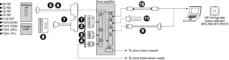
MR-J3-_A/A4 5kW to 22kW (200V) and 3.5kW to 22kW (400V)
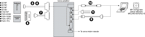
MR-J3-DU_A/A4
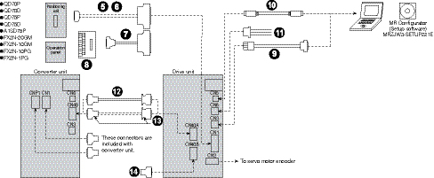
MR-J3-_A-RJ158
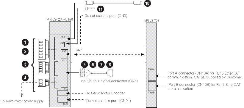
MR-J3-A Type Cables and Connectors (Refer to Charts Above)
CNP_ Connectors (Comes with J3 Amp Standard)
|
Item |
Model Number |
Stocked Lengths |
Protection Level |
Description |
|
|
|
CNP1 Connector 1kW or Less (200VAC) |
54928-0670 |
S |
- |
|
|
CNP1 Connector 2kW - 3.5kW (200VAC)* |
PC4/6-STF-7.62 |
S |
- |
||
|
CNP1 Connector 2kW (200V) (Manufactured after January 2008) |
721-207/026-000 |
S |
- |
||
|
CNP1 Connector 2kW or Less (400VAC) |
|||||
|
|
CNP2 Connector up to 3.5kW (200VAC)* |
54927-0510 |
S |
- |
|
|
CNP2 Connector 2kW (200V) (Manufactured after January 2008) |
721-205/026-000 |
S |
- |
||
|
CNP2 Connector 2kW or Less (400VAC) |
|||||
|
|
CNP3 Connector 1kW or Less (200VAC) |
54928-0370 |
S |
- |
|
|
CNP3 Connector 2kW - 3.5kW (200VAC)* |
PC4/3-STF-7.62 |
S |
- |
||
|
CNP3 Connector 2kW (200V) (Manufactured after January 2008) |
721-203/026-000 |
S |
- |
||
|
CNP3 Connector 2kW or Less (400VAC) |
|||||
|
|
CNP1-2-3 Insertion Tool (200VAC) |
54932-0000 |
S |
- |
|
|
CNP1-2-3 Insertion Tool (400VAC) |
231-131 |
S |
- |
||


* Use this model for amplifiers manufactured prior to January 2008.
For CN1
|
Item |
Model Number |
Stocked Lengths |
Protection Level |
Description |
|
|
|
CN1 Connector (50 Pin) |
MR-J3CN1 |
S |
- |
|
|
|
CN1 Pigtail Cable (50 Pin) |
MR-J3CCN1CBL-_M _ = cable length 3, 5m |
3, 5 |
- |
|
|
|
Junction Terminal Block Cable |
MR-J2M-CN1TBL_M (_ = cable length 0.5, 1m) (For use with MR-TB50 and MR-TB50MIN Junction Terminal Block) |
05, 1 |
- |
|
|
Junction Terminal Block Cable |
MR-J2M-CN1TBL_M-G |
04, 1 |
- |
||
|
|
Junction Terminal Block |
MR-TB50 |
S |
- |
|
|
MR-TB50MIN (reduced size - width = 145mm (5.71 in)) |
S |
- |
|||

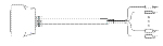

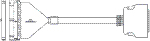


For CN3
|
Item |
Model Number |
Stocked Lengths |
Protection Level |
Description |
|
|
|
RS-232 to RS-485 Converter PC to CN3 (3M) |
SC-FRPC (Cable length 3m) |
S |
- |
|

For CN5
|
Item |
Model Number |
Stocked Lengths |
Protection Level |
Description |
|
|
|
Personal Computer Communication Cable - USB |
MR-J3USBCBL3M Cable length 3m |
S |
- |
|


For CN6A
|
Item |
Model Number |
Stocked Lengths |
Protection Level |
Description |
|
|
|
Monitor Cable |
MR-J3CN6CBL1M Cable length 1m |
S |
- |
|


For CN40 (A/B)
|
Item |
Model Number |
Stocked Lengths |
Protection Level |
Description |
|
|
|
Protection Coordination Cable |
MR-J3CDL05M |
- |
- |
|
|
|
Connector Set |
MR-J2CN1-A |
- |
- |
|
|
|
Terminal Connector |
MR-J3-TM |
- |
- |
|


MR-J3-B Type Amplifier Cables and Connectors
MR-J3-_BS/BS1/BS4 3.5kW or smaller (200V) and 2kW or smaller (400V)
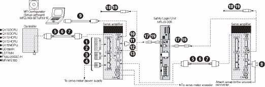
MR-J3-_BS/BS4 5kW to 22kW (200V) and 3.5kW to 22kW (400V)
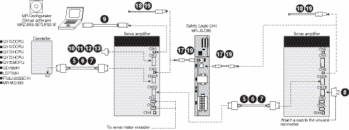
MR-J3-DU_BS/BS4
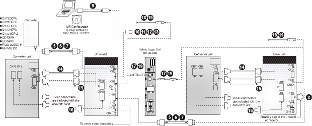
MR-J3-B Safety Type Cables and Connectors (Refer to Charts Above)
CNP_ Connectors (Comes with J3 Amp Standard)
|
Item |
Model Number |
Stocked Item |
Protection Level |
Description |
|
|
|
CNP1 Connector 1kW or Less (200VAC) |
54928-0670 |
S |
- |
|
|
CNP1 Connector 2kW - 3.5kW (200VAC)* |
PC4/6-STF-7.62 |
S |
- |
||
|
CNP1 Connector 2kW (200V) (Manufactured after January 2008) |
721-207/026-000 |
S |
- |
||
|
CNP1 Connector 2kW or Less (400VAC) |
|||||
|
|
CNP2 Connector up to 3.5kW (200VAC)* |
54927-0510 |
S |
- |
|
|
CNP2 Connector 2kW (200V) (Manufactured after January 2008) |
721-205/026-000 |
S |
- |
||
|
CNP2 Connector 2kW or Less (400VAC) |
|||||
|
|
CNP3 Connector 1kW or Less (200VAC) |
54928-0370 |
S |
- |
|
|
CNP3 Connector 2kW - 3.5kW (200VAC)* |
PC4/3-STF-7.62 |
S |
- |
||
|
CNP3 Connector 2kW (200V) (Manufactured after January 2008) |
721-203/026-000 |
S |
- |
||
|
CNP3 Connector 2kW or Less (400VAC) |
|||||
|
|
CNP1-2-3 Insertion Tool (200VAC) |
54932-0000 |
S |
- |
|
|
CNP1-2-3 Insertion Tool (400VAC) |
231-131 |
S |
- |
||
* Use this model for amplifiers manufactured prior to January 2008.
For Controller, CN1A, CN1B B Safety Type Only
|
Item |
Model Number |
Stocked Lengths |
Protection Level |
Description |
|
|
|
SSCNET III Cable (Standard Cord For Inside Panel) |
MR-J3BUS_M _ = cable length 0.15, 0.3, 0.5, 1, 3m |
015, 03, 05, 1, 3 |
- |
|
|
|
SSCNET III Cable (Standard Cable For Outside Panel) |
MR-J3BUS_M-A _ = cable length 5, 10, 20m |
5, 10, 20 |
- |
|
|
|
SSCNET III Cable (Long Distance Cable) |
MR-J3BUS_M-B _ = cable length 30, 40, 50m |
30 |
- |
|

For CN1B
|
Item |
Model Number |
Stocked Item |
Protection Level |
Description |
|
|
|
Connector Cap for SSCNET III |
Connector comes with amplifier standard |
- |
- |
|

For CN5
|
Item |
Model Number |
Stocked Lengths |
Protection Level |
Description |
|
|
|
Personal Computer Communication Cable - USB |
MR-J3USBCBL3M Cable length 3m |
S |
- |
|
For CN3
|
Item |
Model Number |
Stocked Lengths |
Protection Level |
Description |
|
|
|
CN3 Signal Connector (20 Pin) |
MR-J2CN1 |
S |
- |
|
|
|
CN3 Pigtail Cable (20 Pin) |
MR-CCN1CBL-_M _ = cable length 3, 5m |
3, 5 |
- |
|
|
|
Cable for PS7DW-20V14B-F Terminal Block |
MR-J2HBUS_M _ = Cable length 05, 1, 3, 5m |
05, 1, 3, 5 |
- |
|
|
|
20 Pin Terminal Block For J3-B Safety (TB20 Cannot be Used) |
PS7DW-20V14B-F |
S |
- |
|


For CN40
|
Item |
Model Number |
Stocked Lengths |
Protection Level |
Description |
|
|
|
Protection Coordination Cable |
MR-J3CDL05M Cable length: 0.5m |
- |
- |
|
|
|
Connector Set |
MR-J2CN1-A |
- |
- |
|

Connectors
|
Item |
Model Number |
Stocked Item |
Protection Level |
Description |
|
|
|
Terminal Connector for CNB40 |
MR-J3-TM |
- |
- |
|

For CN8 and D05
|
Item |
Model Number |
Stocked Lengths |
Protection Level |
Diagram |
|
|
|
STO Cable (for MR-J3-D05) |
MR-D05UDL_M _ = cable length: 0.3, 1, 3m |
03, 1, 3 |
- |
|
|
|
STO Cable For Safety Control Device Other than MR-J3-D05) (*2) |
MR-D05UDL3M-B |
S |
- |
|
|
|
STO Connector to make Cables 17 and 18 for Custom Lengths (customer supplied cable) |
MR-D05CON |
S |
- |
|
|
|
Short-Circuit Connector (CN8A) |
1971153-1 |
S |
- |
|
|
I/O Connector (CN9) |
Included with Amplifier |
- |
- |
|
|
|
I/O Connector (CN10) |
Included with Amplifier |
- |
- |
|
|


MR-J3-T Type Amplifier Cables and Connectors
MR-J3-_T/T1/T4 3.5kW or smaller (200V) and 2kW or smaller (400V)
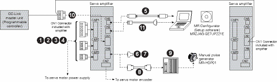
MR-J3-_T/T4 5kW to 22kW (200V) and 3.5kW to 22kW (400V)
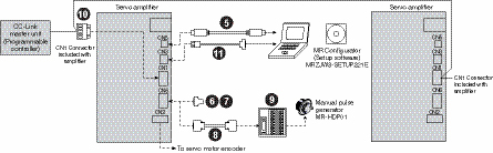
MR-J3-D01 extension IO unit
Options for the servo amplifier are same as when the MR-J3-D01 is not used. Refer to the above illustrations.
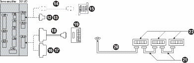
CNP_ Connectors (Comes with J3 Amp Standard)
|
Item |
Model Number |
Stocked Item |
Protection Level |
Description |
|
|
|
CNP1 Connector 1kW or Less (200VAC) |
54928-0670 |
S |
- |
|
|
CNP1 Connector 2kW - 3.5kW (200VAC)* |
PC4/6-STF-7.62 |
S |
- |
||
|
CNP1 Connector 2kW (200V) (Manufactured after January 2008) |
721-207/026-000 |
S |
- |
||
|
CNP1 Connector 2kW or Less (400VAC) |
|||||
|
|
CNP2 Connector up to 3.5kW (200VAC)* |
54927-0510 |
S |
- |
|
|
CNP2 Connector 2kW (200V) (Manufactured after January 2008) |
721-205/026-000 |
S |
- |
||
|
CNP2 Connector 2kW or Less (400VAC) |
|||||
|
|
CNP3 Connector 1kW or Less (200VAC) |
54928-0370 |
S |
- |
|
|
CNP3 Connector 2kW - 3.5kW (200VAC)* |
PC4/3-STF-7.62 |
S |
- |
||
|
CNP3 Connector 2kW (200V) (Manufactured after January 2008) |
721-203/026-000 |
S |
- |
||
|
CNP3 Connector 2kW or Less (400VAC) |
|||||
|
|
CNP1-2-3 Insertion Tool (200VAC) |
54932-0000 |
S |
- |
|
|
CNP1-2-3 Insertion Tool (400VAC) |
231-131 |
S |
- |
||
* Use this model for amplifiers manufactured prior to January 2008.
For CN5
|
Item |
Model Number |
Stocked Lengths |
Protection Level |
Description |
|
|
|
Personal Computer Communication Cable - USB |
MR-J3USBCBL3M (Cable length 3m) |
S |
- |
|
For CN6
|
Item |
Model Number |
Stocked Lengths |
Protection Level |
Description |
|
|
|
CN6 Connector (26 Pin) |
MR-ECN1 |
S |
- |
|
|
|
CN6 Pigtail Cable (26 Pin) |
MR-ECN1CBL-3M |
S |
- |
|
|
|
Junction Terminal Block Cable |
MR-TBNATBL_M (_ = Cable Length: 0.5, 1M) |
05, 1 |
- |
|
|
|
Junction Terminal Block |
MR-TB26A |
S |
- |
|

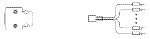


For CN1 and CN3
|
Item |
Model Number |
Stocked Item |
Protection Level |
Description |
|
|
|
CN1 CC-Link Replacement Connector |
1781014 |
- |
- |
|
|
|
RS-232 to RS-485 Converter PC to CN3 (3M) |
SC-FRPC (Cable length 3m) |
S |
- |
|
For CN20
|
Item |
Model Number |
Stocked Lengths |
Protection Level |
Description |
|
|
|
CN20 Signal Connector (20 Pin) |
CN1 |
S |
- |
|
|
|
CN20 Pigtail Cable (20 Pin) |
MR-CCN1CBL-_M (_ = cable length 3, 5m) |
3, 5 |
- |
|
|
|
Cable for PS7DW-20V14B-F Terminal Block |
MR-J2HBUS_M (_ = cable length 05, 1, 3, 5m) |
05, 1, 3, 5 |
- |
|
|
|
20 Pin Terminal Block For J3-B (TB20 Cannot be Used) |
PS7DW-20V14B-F |
S |
- |
|
For CN10
|
Item |
Model Number |
Stocked Lengths |
Protection Level |
Description |
|
|
|
CN10 Connector (50 Pin) |
MR-J3CN1 |
S |
- |
|
|
|
CN10 Pigtail Cable (50 Pin) |
MR-J3CCN1CBL-_M _ = cable length 3, 5m |
3, 5 |
- |
|
|
|
Junction Terminal Block Cable |
MR-J2M-CN1TBL_M (_ = cable length 0.5, 1m) (For use with MR-TB50 and MR-TB50MIN Junction Terminal Block) |
05, 1 |
- |
|
|
Junction Terminal Block Cable |
MR-J2M-CN1TBL_M-G (_ = cable length 0.4, 1m) (For use with MR-TB50 and MR-TB50MIN Junction Terminal Block) |
04, 1 |
- |
||
|
|
Junction Terminal Block |
MR-TB50 (reduced size - width = 244mm (9.61 in)) |
S |
- |
|
|
MR-TB50MIN (reduced size - width = 145mm (5.71 in)) |
S |
- |
|||
Digital Switch Cables
|
Item |
Model Number |
Stocked Lengths |
Protection Level |
Description |
|
|
|
Digital Switch Cable (for between MR-DS60 and MR-J3-D01) |
MR-DSCBL_M-G |
- |
- |
|
|
|
Digital Switch Cable (for between each MR-DS60) |
MR-DSCBL_ |
- |
- |
|
|
|
Digital Switch to Use Together With MR-J3-D01 |
MR-DS60 |
- |
- |
|


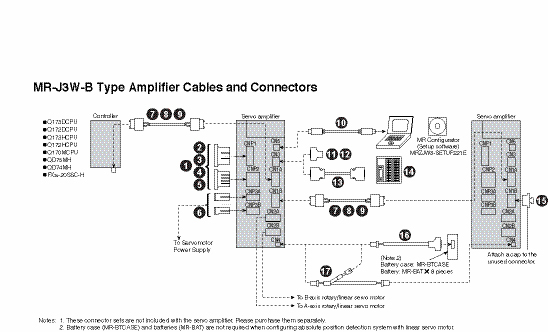
CNP1, CNP2-B(Y), CNP2-A(X) Cables
|
Item |
Model Number |
Stocked Lengths |
Protection Level |
Description |
|
|
|
CNP1 Main Circuit Power Supply Cable |
SC-EMP01CBL_M-L |
2, 5 |
- |
|
|
|
CNP2-B(Y) Control Circuit Power Supply Cable |
SC-ECP01CBL_M-L (_= cable length: 2, 5m) (*1, *2) |
2, 5 |
- |
|
|
|
CNP2-A(X) Built-In Regenerative Resistor Short Connector |
SC-ERG02CBL01M-L |
S |
- |
|
|
|
CNP2-A(X) Optional Regeneration Unit Cable |
SC-ERG01CBL_M-L (_= cable length: 2, 5m)(*1, *2) |
2, 5 |
- |
|

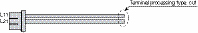

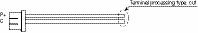
Note:
- Unlisted length is also available per meter: up to 10m for servo amplifier power supply cable and up to 30m for motor power supply cable.
- -H and -L indicate a bending life. -H indicates a long bending life, and -L indicates a standard bending life.
CNP1/CNP2,CNP3A/B Connectors
|
Item |
Model Number |
Stocked Item |
Protection Level |
Description |
|
|
|
CNP1/CNP2 Main Circuit Power Supply Connector Set (Crimp Type) |
MR-J3WCNP12-DM |
S |
- |
|
|
|
CNP3A/B Connector (Crimp Type) |
MR-J3WCNP3-DL |
S |
- |
|
|
CNP1/CNP2/CNP3A/B Connector Set (Spring ClampType with Open Tool included) |
MR-J3WCNP123-SP |
S |
- |
|
|


For Controller, CN1A, CN1B
|
Item |
Model Number |
Stocked Lengths |
Protection Level |
Description |
|
|
|
SSCNET III Cable (Standard Cord For Inside Panel) |
MR-J3BUS_M _ = cable length 0.15, 0.3, 0.5, 1, 3m |
015, 03, 05, 1, 3 |
- |
|
|
|
SSCNET III Cable (Standard Cable For Outside Panel) |
MR-J3BUS_M-A _ = cable length 5, 10, 20m |
5, 10, 20 |
- |
|
|
|
SSCNET III Cable (Long Distance Cable) |
MR-J3BUS_M-B _ = cable length 30, 40, 50m |
30 |
- |
|
For CN5
|
Item |
Model Number |
Stocked Lengths |
Protection Level |
Description |
|
|
|
Personal Computer Communication Cable - USB |
MR-J3USBCBL3M Cable length 3m |
S |
- |
|
For CN3
|
Item |
Model Number |
Stocked Lengths |
Protection Level |
Description |
|
|
|
CN3 Connector (26 Pin) |
MR-ECN1 |
S |
- |
|
|
|
CN6 Pigtail Cable (26 Pin) |
MR-ECN1CBL-3M |
S |
- |
|
|
|
Junction Terminal Block Cable |
MR-TBNATBL_M _=cable length: 0.5, 1m |
05, |
- |
|
|
|
Junction Terminal Block |
MR-TB26A |
S |
- |
|
For CN1B
|
Item |
Model Number |
Stocked Item |
Protection Level |
Description |
|
|
|
Connector Cap for SSCNET III |
Connector comes with amplifier standard |
- |
- |
|
For CN4
|
Item |
Model Number |
Stocked Lengths |
Protection Level |
Description |
|
|
|
Battery Connection Cable |
MR-J3BT1CBL_M _=cable length: 0.3, 1m |
03, 1 |
- |
|
|
|
Battery Connection Relay Cable (*1) |
MR-J3BT2CBL_M _=cable length: 0.3, 1m |
03, 1 |
- |
|

Note:
- Up to 4 units (8 axes) of MR-J3W-_B servo amplifiers are connectable by using this cable.
MR-J3 Motor Cables and Connectors
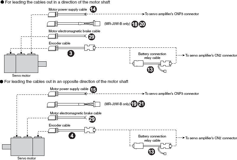
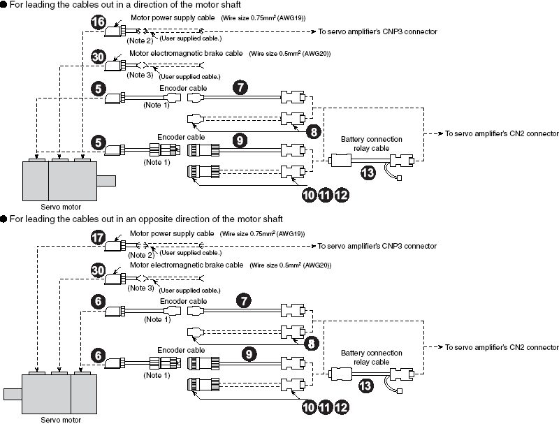
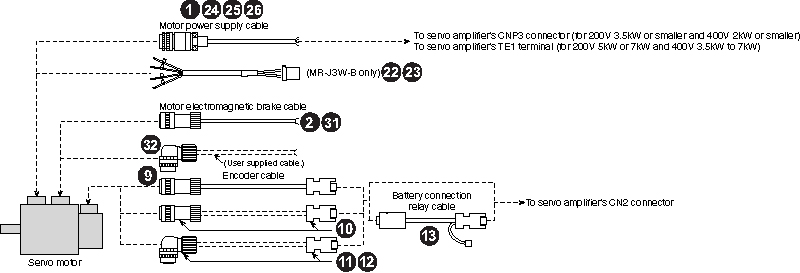
Notes:
- This cable does not have a long bending life, so always fix the cable before using.
- If the length exceeds 10m, relay a cable using MR-PWS2CBL03M-A1-L/-A2-L cable. This cable does not have a long bending life, so always fix the cable before using. Refer to “MR-J3 SERVO AMPLIFIER INSTRUCTION MANUAL” for details on manufacturing the relay cable.
- If the length exceeds 10m, relay a cable using MR-BKS2CBL03M-A1-L/-A2-L cable. This cable does not have a long bending life, so always fix the cable before using. Refer to “MR-J3 SERVO AMPLIFIER INSTRUCTION MANUAL” for details on manufacturing the relay cable.
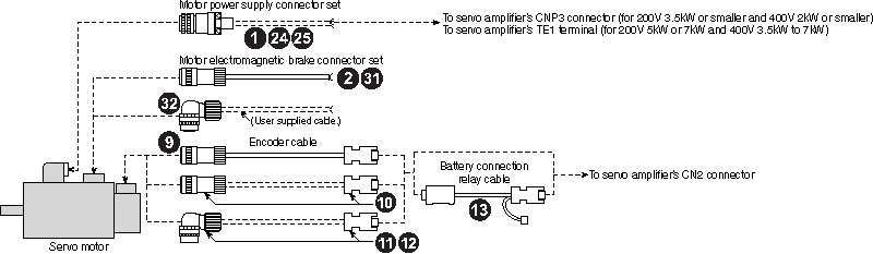
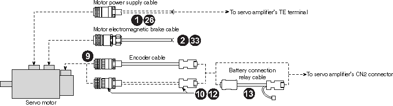
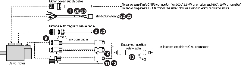
Notes:
- An electromagnetic brake connector set is not required for HC-RP series and 1.5kW or smaller of HC-LP/HC-UP series as the power supply connector has electromagnetic brake terminals.
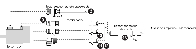
Notes:
- HA-LP502 and 702 are excluded.
- Servomotors with an electromagnetic brake are available in 12kW or smaller for HA-LP 1000r/min series, 15kW or smaller for HA-LP 1500r/min series and 11kW to 22kW for HA-LP 2000r/min series.
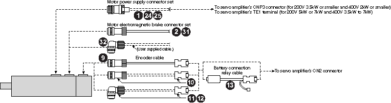
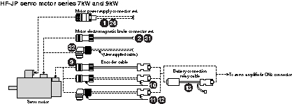
MR-J3 Cables and Connectors (Refer to Charts Above)
Power Cables for HA-LP, HC-LP, HC-RP, HC-UP, HF-SP and HF-JP Series Motors A-, B Safety & T-Type Amplifiers
|
Item |
Motor Model Number |
Cable Number ( _ = cable length 2, 5, 10, 15, 20, 25, 30 meter) |
Stocked Lengths |
Protection Level |
Description |
|
|
|
Standard-Flex, Unshielded Type Cables (Straight Type Connector Only) (*2) |
HA-LP502 |
MR-J3HC5S-_M |
2, 5, 10, 20, 30 |
IP65 |
|
|
HA-LP702 |
MR-J3P7-_M |
|||||
|
HA-LP ALL OTHERS |
Hard Wired By Customer |
N/A |
N/A |
|||
|
HC-LP52 |
MR-J3HC1S-_M |
2, 5, 10, 20, 30 |
IP65 |
|||
|
HC-LP52B |
MR-J3HC1SB-_M |
|||||
|
HC-LP102~152 |
MR-J3HC2S-_M |
|||||
|
HC-LP102B~152B |
MR-J3HC2SB-_M |
|||||
|
HC-LP202(B) (*1) |
MR-J3HC4S-_M |
|||||
|
HC-LP302(B) (*1) |
MR-J3HC5S-_M |
|||||
|
HC-RP103~153 |
MR-J3HC2S-_M |
2, 5, 10, 20, 30 |
IP65 |
|||
|
HC-RP103B~153B |
MR-J3HC2SB-_M |
|||||
|
HC-RP203 |
MR-J3HC3S-_M |
|||||
|
HC-RP203B |
MR-J3HC3SB-_M |
|||||
|
HC-RP353~503 |
MR-J3HC5S-_M |
|||||
|
HC-RP353B~503B |
MR-J3HC5SB-_M |
|||||
|
HC-UP72 |
MR-J3HC1S-_M |
2, 5, 10, 20, 30 |
IP65 |
|||
|
HC-UP72B |
MR-J3HC1SB-_M |
|||||
|
HC-UP152 |
MR-J3HC2S-_M |
|||||
|
HC-UP152B |
MR-J3HC2SB-_M |
|||||
|
HC-UP202(B) (*1) |
MR-J3HC4S-_M |
|||||
|
HC-UP352(B)~502(B) (*1) |
MR-J3HC5S-_M |
|||||
|
HF-SP51, HF-SP51B, HF-SP52, HF-SP52B, HF-SP524, HF-SP524B, HF-SP1024, HF-SP1024B (*1) |
MR-J3P1-_M |
2, 5, 10, 20, 30 |
IP65 |
|||
|
HF-JP53, HF-JP53B, HF-JP534, HF-JP534B, HF-JP73, HF-JP73B, HF-JP734, HF-JP734B, HF-JP1034, HF-JP1034B (*1) |
MR-J3P1-_M |
|||||
|
HF-SP81, HF-SP81B, HF-SP102, HF-SF102B, HF-SP152, HF-SP 152B, HF-SP1524, HF-SP1524B, HF-JP103, HF-JP103B, HF-JP153, HF-JP153B, HF-JP1534, HF-JP1534B, GSX20, GSX30 (*1) |
MR-J3P2-_M |
|||||
|
HF-SP121, HF-SP121B, HF-201, HF-SP201B, HF-SP202, HF-SP202B, HF-SP2024, HF-2024B (*1) |
MR-J3P4-_M |
|||||
|
HF-SP502, HF-SP502B, HF-5024, HF-SP502B, GSX40, GSX50 (*1) |
MR-J3P6-_M |
|||||
|
HF-SP421, HF-SP421B, HF-SP702, HF-SP702B, HF-SP7024, HF-SP7024B, HF-JP703, HF-JP703B, HF-JP7034, HF-JP7034B, HF-JP9034, HF-JP9034B, HF-JP11K1M4, HF-JP11K1M4B, GSX60 (*1) |
MR-J3P7-_M |
|||||
|
HF-JP203, HF-JP203B, HF-JP2034, HF-JP2034B, HF-JP3534, HF-JP3534B (*1) |
MR-J3P8-_M |
|||||
|
HF-SP301, HF-SP301B, HF-SP352, HF-352B, HF-SP3524, HF-SP3524B, HF-JP353, HF-JP353B (*1) |
MR-J3P9-_M |
|||||
|
HF-JP503, HF-JP503B (*1) |
MR-J3P10-_M |
|||||
|
HF-JP5034, HF-JP5034B (*1) |
MR-J3P11-_M |
|||||
|
HF-JP903, HF-JP903B, HF-JP11K1M, HF-JP11K1MB, HF-JP15K1M4, HF-JP15K1M4B (*1) |
MR-J3P12-_M |
- |
||||
|
HF-JP15K1M, HF-JP15K1MB (*1) |
MR-J3P13-_M |
|||||
|
Item |
Motor Model Number |
Cable Number ( _ = cable length 2, 5, 10, 15, 20, 25, 30 meter) |
Stocked Lengths |
Protection Level |
Description |
|
|
|
High-Flex, Shielded Type Cables (Straight Type Connector Only) (*2) |
HA-LP502 |
MR-J3HC5S-SH-_M |
- |
IP65 |
|
|
HA-LP702 |
MR-J3PWS7-_M |
|||||
|
HA-LP ALL OTHERS |
Hard Wired By Customer |
N/A |
N/A |
|||
|
HC-LP52 |
MR-J3HC1S-SH-_M |
- |
IP65 |
|||
|
HC-LP52B |
MR-J3HC1SB-SH-_M |
|||||
|
HC-LP102~152 |
MR-J3HC2S-SH-_M |
|||||
|
HC-LP102B~152B |
MR-J3HC2SB-SH-_M |
|||||
|
HC-LP202(B) (*1) |
MR-J3HC4S-SH-_M |
|||||
|
HC-LP302(B) (*1) |
MR-J3HC5S-SH-_M |
|||||
|
HC-RP103~153 |
MR-J3HC2S-SH-_M |
- |
IP65 |
|||
|
HC-RP103B~153B |
MR-J3HC2SB-SH-_M |
|||||
|
HC-RP203 |
MR-J3HC3S-SH-_M |
|||||
|
HC-RP203B |
MR-J3HC3SB-SH-_M |
|||||
|
HC-RP353~503 |
MR-J3HC5S-SH-_M |
|||||
|
HC-RP353B~503B |
MR-J3HC5SB-SH-_M |
|||||
|
HC-UP72 |
MR-J3HC1S-SH-_M |
- |
IP65 |
|||
|
HC-UP72B |
MR-J3HC1SB-SH-_M |
|||||
|
HC-UP152 |
MR-J3HC2S-SH-_M |
|||||
|
HC-UP152B |
MR-J3HC2SB-SH-_M |
|||||
|
HC-UP202(B) (*1) |
MR-J3HC4S-SH-_M |
|||||
|
HC-UP352(B)~502(B) (*1) |
MR-J3HC5S-SH-_M |
|||||
|
HF-SP51, HF-SP51B, HF-SP52, HF-SP52B, HF-SP524, |
MR-J3PWS1-_M |
2, 5 10, 15, 20, 30 |
IP67 |
|||
|
HF-JP53, HF-JP53B, HF-JP534, HF-JP534B, HF-JP73, |
MR-J3PWS1-_M |
|||||
|
HF-SP81, HF-SP81B, HF-SP102, HF-SF102B, HF-SP152, HF-SP 152B, HF-SP1524, HF-SP1524B, HF-JP103, HF-JP103B, HF-JP153, HF-JP153B, HF-JP1534, HF-JP1534B, GSX20, GSX30 (*1) |
MR-J3PWS2-_M |
|||||
|
HF-SP121, HF-SP121B, HF-201, HF-SP201B, HF-SP202, |
MR-J3PWS4-_M |
|||||
|
HF-SP502, HF-SP502B, HF-5024, HF-SP502B, GSX40, GSX50 (*1) |
MR-J3PWS6-_M |
|||||
|
HF-SP421, HF-SP421B, HF-SP702, HF-SP702B, HF-SP7024, HF-SP7024B, HF-JP703, HF-JP703B, HF-JP7034, HF-JP7034B, HF-JP9034, HF-JP9034B, HF-JP11K1M4, HF-JP11K1M4B, GSX60 (*1) |
MR-J3PWS7-_M |
|||||
|
HF-JP203, HF-JP203B, HF-JP2034, HF-JP2034B, HF-JP3534, HF-JP3534B (*1) |
MR-J3PWS8-_M |
|||||
|
HF-SP301, HF-SP301B, HF-SP352, HF-352B, HF-SP3524, |
MR-J3PWS9-_M |
|||||
|
HF-JP503, HF-JP503B (*1) |
MR-J3PWS10-_M |
|||||
|
HF-JP5034, HF-JP5034B (*1) |
MR-J3PWS11-_M |
|||||
|
HF-JP903, HF-JP903B, HF-JP11K1M, HF-JP11K1MB, HF-JP15K1M4, HF-JP15K1M4B (*1) |
MR-J3PWS12-_M |
|||||
|
HF-JP15K1M, HF-JP15K1MB (*1) |
MR-J3PWS13-_M |
- |
||||
|
HF-JP15K1M(B) (*1) |
MR-J3PWS13-_M |
|||||

Note:
- Must order separate brake cable for these motors.
- Standard-flex cables listed on previous page.
Brake Cables for - A-, B Safety & T-Type Amplifiers
|
Item |
Motor Model Number |
Cable Number ( _ = cable length 2, 5, 10, 15, 20, 25, 30 Meter) |
Stocked Lengths |
Protection Level |
Description |
|
|
|
Standard-Flex, Unshielded Type Cables |
HA-LP ALL (B) SIZES |
MR-J3HCBKS-_M |
2, 5, 10, 20, 30 |
IP65 |
|
|
HC-LP202B, 302B |
||||||
|
HC-UP202B, 352B, 502B |
||||||
|
HF-JP11K1M(4)B~HF-JP15K1M(4)B |
||||||
|
HF-SP(4) ALL (B) SIZES |
MR-J3BK-_M |
IP67 |
||||
|
HF-JP53B~HF-JP9034B |
||||||
|
GSX Actuators |
||||||
|
High-Flex, Shielded Type Cables |
HA-LP ALL (B) SIZES |
MR-J3HCBKS-SH-_M |
- |
IP65 |
|
|
|
HC-LP202B, 302B |
||||||
|
HC-UP202B, 352B, 502B |
||||||
|
HF-JP11K1M(4)B~HF-JP15K1M(4)B |
||||||
|
HF-SP(4) ALL (B) SIZES |
MR-J3BRKS1-_M |
2, 5, 10, 15, 20, 30 |
IP67 |
|||
|
HF-JP53B~HF-JP9034B |
||||||
|
GSX Actuators |
||||||

Encoder Cables for A-, B Safety and T-Type
|
Item |
Model |
Stocked Lengths |
Protection Level |
Description |
||
|
|
10m or Shorter (Direct Connection Type) |
Encoder Cable For HF-MP/HF-KP Series Motor Lead Out In Direction Of Motor Shaft |
MR-J3ENCBL_M-A1-H _ = cable length 2, 5, 10m (*1) |
2, 5, 10 |
IP65 |
|
|
MR-J3ENCBL_M-A1-L _ = cable length 2, 5, 10m (*1) |
2, 5, 10 |
IP65 |
||||
|
|
Encoder Cable For HF-MP/HF-KP Series Motor Lead Out In Opposite Direction Of Motor Shaft |
MR-J3ENCBL_M-A2-H _ = cable length 2, 5, 10m (*1) |
2, 5, 10 |
IP65 |
||
|
MR-J3ENCBL_M-A2-L _ = cable length 2, 5, 10m (*1) |
2, 5, 10 |
IP65 |
||||
|
|
Exceeding 10m (Relay Type) |
Encoder Cable For HF-MP/HF-KP Series Motor Lead Out In Direction Of Motor Shaft |
MR-J3JCBL03M-A1-L Cable length 0.3m (*1) |
S |
IP20 |
|
|
MR-J3JSCBL03M-A1-L Cable length 0.3m (*1, *3) |
S |
IP67 |
|
|||
|
|
Encoder Cable For HF-MP/HF-KP Series Motor Lead Out In Opposite Direction Of Motor Shaft |
MR-J3JCBL03M-A2-L Cable length 0.3m (*1) |
S |
IP20 |
|
|
|
MR-J3JSCBL03M-A2-L Cable length 0.3m (*1, *3) |
S |
IP67 |
|
|||
|
|
Amplifier-Side Cable For HF-MP/HF-KP Series Motor |
MR-EKCBL_M-H _ = cable length 20, 30, 40, 50m (*1) |
20, 30 |
IP20 |
|
|
|
MR-EKCBL_M-L _ = cable length 20, 30m (*1) |
- |
IP20 |
||||
|
|
Junction Connector, Amplifier-Side Connector (*2) For HF-MP/HF-KP Series Motor |
MR-ECNM |
S |
IP20 |
|
|
|
|
Encoder Cable For HF-SP, HC-RP, HC-UP, HC-LP, HA-LP, HF-JP53(B)~HF-JP9034(B) Series Motor, GSX Actuators |
MR-J3ENSCBL_M-H _ = cable length 2, 5, 10, 20, 30, 40, 50m (*1) |
2, 5, 10, 20, 30 |
IP67 |
|
|
|
MR-J3ENSCBL_M-L _ = cable length 2, 5, 10, 20, 30m (*1) |
2, 5 |
IP67 |
||||
|
Encoder cable for HF-JP11K1M, 15K1M, 11K1M4, 15K1M4, GSX Actuators |
MR-ENECBL_M-H _= 2, 5, 10, 20, 30, 40, or 50 (*1) |
2, 5, 10 |
IP67 |
|||
|
MR-ENECBL_M-L _= 2, 5, 10, 20, 30, 40, or 50 (*1) |
- |
IP67 |
||||
|
|
Encoder connector set for HF-SP/HC-LP/HC-RP/HC-UP/HA-LP Series HF-JP53, 73, 103, 153, 203, 353, 503, 703, 903534, 734, 1034, 1534, 2034, 3534, 5034, 7034, 9034, GSX Actuators |
MR-J3SCNS |
S |
IP67 |
|
|
|
Encoder connector set for HF-JP11K1M, 15K1M, 11K1M4, 15K1M4, GSX Actuators |
MR-ENECNS |
S |
IP67 |
|||
|
|
90° Encoder connector set for HF-SP/HC-LP/HC-RP/HC-UP/HA-LP Series HF-JP53, 73, 103, 153, 203, 353, 503, 703, 903534, 734, 1034, 1534, 2034, 3534, 5034, 7034, 9034, GSX Actuators |
MR-J3SCNSA |
S |
IP67 |
|
|
|
|
CN2 or CN2L Connector, GSX Actuators |
MR-J3CN2 |
S |
IP20 |
|
|
|
|
Battery Connection Relay Cable, GSX Actuators |
MR-J3BTCBL03M Cable length 0.3m |
S |
- |
|
|
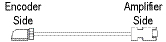
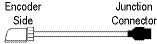

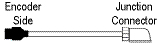
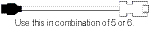


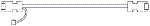
Notes:
- -H and -L indicate a bending life. -H indicates a long bending life, and -L indicates a standard bending life.
- The IP rating indicated is for the connector’s protection against ingress of dust and water when coupled to a servo amplifier/servomotor. If the IP rating of the servo amplifier/servomotor differs from that of these connectors, overall IP rating depends on the lowest of all.
- The encoder cable is rated IP65 while the junction connector is rated IP67.
Motor Power Supply Cables For CNP3 - A-, B Safety and T-Type
|
Item |
Model (*1) |
Stocked Lengths |
Protection Level |
Description |
||
|
|
10m Or Shorter (Direct Connection Type |
Power Supply Cable For HF-MP/ HF-KP Series Motor. Lead Out In Direction Of Motor Shaft (Non-shielded) |
MR-PWS1CBL_M-A1-H (_ = cable length 2, 5, 10m) |
2, 5, 10 |
IP65 |
|
|
MR-PWS1CBL_M-A1-L (_ = cable length 2, 5, 10m _ |
2, 5, 10 |
IP65 |
||||
|
Power Supply Cable For HF-MP/ HF-KP Series Motor. Lead Out In Direction Of Motor Shaft (Shielded) |
MR-J3PS_M-A1 |
5 |
IP65 |
|||
|
|
Power Supply Cable For HF-MP/ HF-KP Series Motor. Lead Out In Opposite Direction of Motor Shaft (Non-shielded) |
MR-PWS1CBL_M-A2-H (_ = cable length 2, 5, 10m) |
2, 5, 10 |
IP65 |
||
|
MR-PWS1CBL_M-A2-L (_ = cable length 2, 5, 10m) |
2, 5, 10 |
IP65 |
||||
|
Power Supply Cable For HF-MP/ HF-KP Series Motor. Lead Out In Opposite Direction of Motor Shaft (Shielded) |
MR-J3PS_M-A2 |
5, 10 |
IP65 |
|||
|
|
Exceeding 10m (Relay Type) |
Power Supply Cable For HF-MP/HF-KP Series Motor Lead Out In Direction Of Motor Shaft (Non-Shielded) |
MR-PWS2CBL03M-A1-L (Cable length 0.3m) |
S |
IP55 |
|
|
Power Supply Cable For HF-MP/HF-KP Series Motor Lead Out In Direction Of Motor Shaft (Shielded) |
MR-J3PS03M-A1 |
S |
IP55 |
|||
|
|
Power Supply Cable For HF-MP/HF-KP Series Motor Lead Out In Opposite Direction Of Motor Shaft (Non-Shielded) |
MR-PWS2CBL03M-A2-L (Cable length 0.3m) |
S |
IP55 |
||
|
Power Supply Cable For HF-MP/HF-KP Series Motor Lead Out In Opposite Direction Of Motor Shaft (Shielded) |
MR-J3PS03M-A2 |
S |
IP55 |
|||
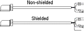

Note:
- -H and -L indicate bending life. -H indicates a long bending life and -L indicates a standard bending life.
Power Supply Cable for HF-KP/HF-MP Rotary Servomotor Series (Direct Connection Type)
|
Item |
Model (*1) |
Stocked Lengths |
Protection Level |
Description |
|
|
|
Lead Out in Direction of Motor Shaft Standard Bending Life |
SC-EPWS1CBL_M-A1-L (_= cable length: 2, 5, 10m) |
- |
- |
|
|
|
Lead Out in Opposite Direction of Motor Shaft Standard Bending Life |
SC-EPWS1CBL_M-A2-L (_= cable length: 2, 5, 10m) |
- |
- |
|
|
|
Lead Out in Direction of Motor Shaft Long Bending Life |
SC-EPWS1CBL_M-A1-H (_= cable length: 2, 5, 10m) |
2, 5, 10 |
- |
|
|
|
Lead out in Opposite Direction of Motor Shaft Long Bending Life |
SC-EPWS1CBL_M-A2-H (_= cable length: 2, 5, 10m) |
2, 5, 10 |
- |
|
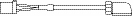
Power Supply Cable for HF-SP/HC-LP/HC-UP Rotary Servomotor Series
|
Item |
Model (*1) |
Stocked Lengths |
Protection Level |
Description |
|
|
|
Standard Bending Life |
SC-EPWS2CBL_M-L (_= cable length: 2, 5, 10, 20, 30m) |
- |
- |
|
|
|
Long Bending Life |
SC-EPWS2CBL_M-H (_= cable length: 2, 5, 10, 20, 30m) |
2, 5, 10 |
- |
|

Note:
- A separate motor-side power supply connector (listed below) is required for HF-SP/HC-LP/HC-UP rotary servomotors.
Power Supply Connectors
|
Item |
Model Number |
Stocked Lengths |
Protection Level |
Diagram |
|
|
|
Power Supply Connector Set for HF-SP51, 81, 52, 102, 152, 524, 1024, 1524, HF-JP53, 73, 103, 153, 203, 534, 734, 1034, 1534, 2034, 3534, 5034, GSX20, GSX30 |
MR-PWCNS4 (straight type only) |
S |
IP67 |
|
|
|
Power Supply Connector Set for HF-SP121, 201, 301, 202, 352, 502, 2024, 3524, 5024, HF-JP353, 503, GSX40, GSX50 |
MR-PWCNS5 (straight type only) |
S |
IP67 |
|
|
|
Power Supply Connector Set for HF-SP421, 702, 7024, HF-JP703, 903, 7034, 9034, HF-JP11K1M, 15K1M,11K1M4, 15K1M4, HA-LP702, GSX60 |
MR-PWCNS3 (Straight type only) |
S |
IP67 |
|
|
|
Power Supply Connector Set for HC-LP52, 102, 152, HC-RP103, 153, 203, HC-UP72, 152, |
MR-PWCNS1 (Straight type) |
S |
IP67 |
|
|
|
Power Supply Connector Set for HC-LP202, 302, HC-RP353, 503, HC-UP202, 352, 502, HA-LP502 |
MR-PWCNS2 (Straight type) |
S |
IP67 |
|


MR-J3 Cables and Connectors Continued (Refer to Chart on Previous Page)
Motor Brake Cables
|
Item |
Model Number |
Stocked Lengths |
Protection Level |
Diagram |
||
|
|
Brake Cable for HF-KP/HF-MP Series 10m or Shorter (Direct Connection Type) |
Lead Out in Direction of Motor Shaft |
MR-BKS1CBL_M-A1-H (_= 2, 5, or 10) (*1) |
2, 5, 10 |
IP65 |
|
|
MR-BKS1CBL_M-A1-L (_= 2, 5, or 10) (*1) |
- |
IP65 |
||||
|
Lead Out in Opposite Direction of Motor Shaft |
MR-BKS1CBL_M-A2-H (_= 2, 5, or 10) (*1) |
2, 5, 10 |
IP65 |
|||
|
MR-BKS1CBL_M-A2-L _= 2, 5, or 10 (*1) |
- |
IP65 |
||||
|
|
Brake Cable for HF-KP/HF-MP Series Exceeding 10m (Relay Type) |
Lead Out in Direction of Motor Shaft |
MR-BKS2CBL03M-A1-L (cable length 0.3) (*1) |
S |
IP55 |
|
|
Lead Out in Opposite Direction of Motor Shaft |
MR-BKS2CBL03M-A2-L (cable length 0.3) (*1) |
S |
IP55 |
|||


Note:
- -H and -L indicate bending life. -H indicates a long bending life and -L indicates a standard bending life.
Brake Connector Set
|
Item |
Model Number |
Stocked Lengths |
Protection Level (*1) |
Diagram |
|
|
|
Brake Connector Set for HF-SP Series, |
MR-BKCNS1 (straight type only) |
S |
IP67 |
|
|
|
Brake Connector Set for HF-SP Series, |
MR-BKCNS1A (Angled type) |
S |
IP67 |
|
|
|
Brake Connector Set for HF-JP11K1MB, 15K1MB, 11K1M4B, 15K1M4B, HC-LP202B, 302B, HC-UP202B, 352B, 502B, HA-LP601B, 801B, 12K1B, 6014B, 8014B, 12K14B, 701MB,11K1MB, 15K1MB, 701M4B, 11K1M4B, 15K1M4B, 11K2B, 15K2B, 22K2B, 11K24B, 15K24B, 22K24B |
MR-BKCN |
S |
IP65 |
|


Note:
- The IP rating indicated is for the connector’s protection against ingress of dust and water when coupled to a servo amplifier/servomotor. If the IP rating of the servo amplifier/servomotor differs from that of these connectors, overall IP rating depends on the lowest of all.
Software and Manuals
MR-CONFIGURATOR2 • (MRZJW3-MOTSZ111E)
This software makes it easy to perform setup, tuning, monitor display, diagnostics, reading and writing of parameters, and test operations with a personal computer. User-satisfying functions that enable the balance with the machine system, optimum control and short start up time are available.
- This software can set up and tune your servo system easily with a personal computer.
- Multiple monitor functions. Graphic display functions are provided to display the servomotor status with the input signal triggers, such as the command pulse, droop pulse and speed.
- Test operations with a personal computer. Test operation of the servomotors can be performed with a personal computer using multiple test mode menus.
- Further advanced tuning is possible with the improved advanced functions.
Manuals
|
Hardware Description |
Model Number |
Stocked Item |
|
MR-J3-A Instruction Manual |
SH(NA)030038 |
MEAU.com |
|
MR-J3-B Safety Instruction Manual |
SH(NA)030051 |
MEAU.com |
|
MR-J3-T Instruction Manual |
SH(NA)030058 |
MEAU.com |
|
MR-J3-T / MR-J3-D01 Instruction Manual |
SH(NA)030061 |
MEAU.com |
|
Servomotor Manual Volume 2 |
SH(NA)030041 |
MEAU.com |
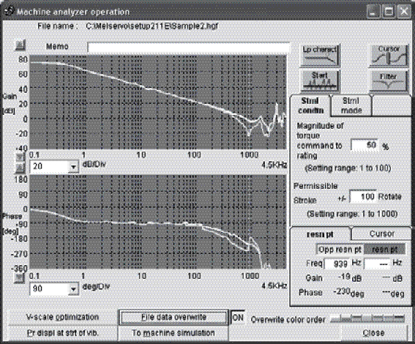
|
Description |
Model Number |
Stocked Item |
|
Windows Communication Software |
MR-CONFIGURATOR2 |
S |
|
Communication Cable |
MR-J3USBCBL3M |
S |
System Options
Extension I/O Unit
|
Servo Amplifier Type |
Model Number |
Stocked Item |
Description |
|
MR-J3-T Only |
MR-J3-D01 |
S |
|
|
MR-J3-B Safety Only |
MR-J3-D05 |
S |
|

I/O Digital Switch
|
Servo Amplifier Type |
Model Number |
Stocked Item |
Description |
|
MR-J3-D01 Only |
MR-DS60 |
- |
|
RS-422 Distributor (For Multidrop)
|
Servo Amplifier Type |
Model Number |
Stocked Item |
Description |
|
MR-J3-A/B Safety/T |
BMJ-8 |
S |
|

Manual Pulse Generator
|
Servo Amplifier Type |
Model Number |
Stocked Item |
Description |
|
MR-J3-T Only |
MR-HDP01 |
S |
|

20 Pin Terminal Block (*1)
|
Servo Amplifier Type |
Model Number |
Stocked Item |
Description |
|
MR-J3-B Safety Only |
PS7DW-20V14B-F |
S |
|

Note: 1. MR-TB20 terminal block cannot be used for MR-J3-B Safety.
Heat Sink Mounting Attachment
|
Servo Amplifier Type |
Model Number |
Stocked Item |
Description |
|
MR-J3-11K to 22KA/B Safety /T Only |
MR-J3ACN |
- |
|
MR-J3-A-RJ158 (EtherCAT)
|
Servo Amplifier Type |
Model Number |
Stocked Item |
Description |
|
MR-J3-A Only |
MR-J3-T04 |
S |
|
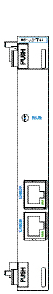
|
Item Number |
Model Number |
Description |
Stocked Item |
Description |
|
Battery |
MR-J3BAT |
The servomotor’s absolute value can be maintained by installing the battery in the servo amplifier. The battery is not required when the servo system is used in an incremental mode. |
S |
|
|
Battery Connection Relay Cable |
MR-J3BTCBL03M |
Use this relay cable to hold the absolute value when shipping the product with the machine and servo amplifier removed. The servomotor HF series does not have a super capacitor (for holding an absolute value for short time) in the encoder. When this optional cable is used, the absolute value can be held even when the encoder cable is disconnected from the servo amplifier, making it easy to do maintenance on the servo amplifier. |
S |
|
|
Diagnostic Cable |
MR-J3ACHECK |
This cable is required when using the amplifier diagnostic function of MR Configurator (Setup software). |
S |
|

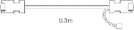
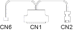
Line Noise Filter
|
Servo Amplifier Type |
Model Number |
Stocked Item |
Description |
|
MR-J3-200A/B Safety/T(4) or Smaller |
FR-BSF01 |
S |
|
|
MR-J3-350A/B Safety/ T(4) or Larger |
FR-BLF |
S |

Radio Noise Filter
|
Servo Amplifier Type |
Model Number |
Stocked Item |
Description |
|
All 200VAC J3 Models |
FR-BIF |
S |
|
|
All 400VAC J3 Models |
FR-BIF-H |
- |

Brake/Resistor Units (Must be used in conjunction with each other)
|
Servo Amplifier Model |
Brake Unit Model Number |
Stocked Item |
Resistor Unit Model Number |
Stock Item |
|
MR-J3-500A/BS/T to 700A/BS/T |
FR-BU2-15K |
S |
FR-BR-15K-UL |
S |
|
MR-J3-11KA/BS/T to 15KA/BS/T |
FR-BU2-30K |
S |
FR-BR-30K-UL |
S |
|
MR-J3-22KA/BS/T |
FR-BU2-55K |
- |
FR-BR-55K-UL |
- |
|
MR-J3-500 ~ 700A4/BS4/T4 |
FR-BU2-H15K |
S |
FR-BR-H15K-UL |
S |
|
MR-J3-11K ~ 15KA4/BS4/T4 |
FR-BU2-H30K |
S |
FR-BR-H30K-UL |
S |
|
MR-J3-22KA4/BS4/T4 |
FR-BU2-H55K |
- |
FR-BR-H55K-UL |
S |
Power Regeneration Common Converter/Stand-Alone Reactor
(Must be used in conjunction with each other). Up to six servo amplifiers can be connected to one FR-CV, refer to manuals for details.
|
Servo Amplifier Model |
Common Converter Model Number |
Stocked Item |
Reactor Model Number |
Stock Item |
|
MR-J3-350A/B/T |
FR-CV-7.5K |
- |
FR-CVL-7.5K |
- |
|
MR-J3-500A/B/T |
FR-CV-11K |
- |
FR-CVL-11K |
- |
|
MR-J3-700A/B/T |
FR-CV-15K |
- |
FR-CVL-15K |
- |
|
MR-J3-11KA/B/T |
FR-CV-22K |
- |
FR-CVL-22K |
- |
|
MR-J3-15KA/B/T |
FR-CV-30K |
- |
FR-CVL-30K |
- |
|
FR-CV-37K |
- |
FR-CVL-37K |
- |
|
|
MR-J3-22KA/B/T |
FR-CV-55K |
- |
FR-CVL-55K |
- |
EMC Filter
|
Servo Amplifier Type |
Model Number |
Stocked Item |
|
MR-J3-100A/BS/T and less |
MF3F480-010.233MF |
S |
|
MR-J3-200A/BS/T |
MF3F480-015.230MF3 |
S |
|
MR-J3-350A/BS/T |
MF3F480-025.230MF3 |
S |
|
MR-J3-500A/BS/T ~ 700A/BS/T |
MF3F480-050.230MF3 |
S |
|
MR-J3-11KA/BS/T ~ 22KA/BS/T |
HF3100A-UN |
- |
|
MR-J3-DU30 ~ 37KA/BS |
HF3200A-UN |
- |
|
MR-J3-100A4/BS4/T4 and less |
MF3F480-010.233MF |
S |
|
MR-J3-200A4/BS4/T4 |
MF3F480-015.230MF3 |
S |
|
MR-J3-350A4/BS4/T4 |
MF3F480-015.233MF |
S |
|
MR-J3-500A4/BS4/T4 ~ 700A4/BS4/T4 |
MF3F480-025.230MF3 |
S |
|
MR-J3-11KA4/BS4/T4 ~ 15KA4/BS4/T4 |
MF3F480-035.230 |
- |
|
MR-J3-22KA4/BS4/T4 |
MF3F480-050.230MF3 |
S |
|
MR-J3-DU30 ~ 55KA4/BS4 |
TF3150C-TX |
- |
External Dynamic Brake
|
Servo Amplifier Type |
Model Number |
Stocked Item |
Description |
|
MR-J3-11KA/BS/T |
DBU-11K |
- |
|
|
MR-J3-15KA/BS/T |
DBU-15K |
- |
|
|
MR-J3-22KA/BS/T |
DBU-22K |
- |
|
|
MR-J3-11KA4/BS4/T4 |
DBU-11K-4 |
- |
|
|
MR-J3-15K ~ 22KA4/BS4/T4 |
DBU-22K-4 |
S |
|
|
MR-J3-DU30KBS ~ DU37KBS |
DBU-37K |
- |
|
|
MR-J3-DU30KBS4 ~ DU55KBS4 |
DBU-55K-4 |
- |
Power Regeneration Converter
|
Servo Amplifier Type |
Model Number |
Stocked Item |
Description |
|
MR-J3-500A/BS/T |
FR-RC-15K |
- |
|
|
MR-J3-700A/BS/T ~ 15KA/BS/T |
FR-RC-30K |
- |
|
|
MR-J3-22KA/BS/T |
FR-RC-55K |
- |
|
|
MR-J3-500A4/BS4/T4 |
FR-RC-H15K |
- |
|
|
MR-J3-700 ~ 15KA4/BS4/T4 |
FR-RC-H30K |
- |
|
|
MR-J3-22KA4/BS4/T4 |
FR-RC-H55K |
- |
200VAC Optional Regeneration Resistors
|
Servo Amplifier Model MR-J3-_ |
Built-in Regenerative Resistor/Tolerable Regenerative Power (W) |
Standard Resistors Supplied with Amplifiers |
Optional Regeneration Resistors/Tolerable Regenerative Power (W) |
|||||||||||||||
|
GRZG400- |
MR-RB |
|||||||||||||||||
|
0.8ΩX4 (*2) |
0.8ΩX4 (*2) |
0.9ΩX5 (*2) |
0.6ΩX5 (*2) |
032 (40Ω) |
12 (40Ω) |
30 (13Ω) |
31 (6.7Ω) |
32 (40Ω) |
50 (13Ω) (*1) |
51 (6.7Ω)(*1) |
5E (6Ω)(*2) |
5R (3.2Ω)(*2) |
9P (4.5Ω)(*2) |
9F (3Ω)(*2) |
139 (1.3Ω) |
137 (1.3Ω)(*3) |
||
|
Stocked Item |
- |
- |
- |
- |
S |
S |
S |
- |
S |
S |
S |
- |
- |
- |
- |
- |
||
|
10A(1)/BS(1)/T(1) |
- |
- |
- |
- |
- |
30 |
- |
- |
- |
- |
- |
- |
- |
- |
- |
- |
- |
- |
|
20A(1)/BS(1)/T(1) |
10 |
- |
- |
- |
- |
30 |
100 |
- |
- |
- |
- |
- |
- |
- |
- |
- |
- |
- |
|
40A(1)/BS(1)/T(1) |
10 |
- |
- |
- |
- |
30 |
100 |
- |
- |
- |
- |
- |
- |
- |
- |
- |
- |
- |
|
60A/BS/T |
10 |
- |
- |
- |
- |
30 |
100 |
- |
- |
- |
- |
- |
- |
- |
- |
- |
- |
- |
|
70A/BS/T |
20 |
- |
- |
- |
- |
30 |
100 |
- |
- |
300 |
- |
- |
- |
- |
- |
- |
- |
- |
|
100A/BS/T |
20 |
- |
- |
- |
- |
30 |
100 |
- |
- |
300 |
- |
- |
- |
- |
- |
- |
- |
- |
|
200A/BS/T |
100 |
- |
- |
- |
- |
- |
- |
300 |
- |
- |
500 |
- |
- |
- |
- |
- |
- |
- |
|
350A/BS/T |
100 |
- |
- |
- |
- |
- |
- |
300 |
- |
- |
500 |
- |
- |
- |
- |
- |
- |
- |
|
500A/BS/T |
130 |
- |
- |
- |
- |
- |
- |
- |
300 |
- |
- |
500 |
- |
- |
- |
- |
- |
- |
|
700A/BS/T |
170 |
- |
- |
- |
- |
- |
- |
- |
300 |
- |
- |
500 |
- |
- |
- |
- |
- |
- |
|
11KA/BS/T |
- |
500 (800) |
- |
- |
- |
- |
- |
- |
- |
- |
- |
- |
500 (800) |
- |
- |
- |
- |
- |
|
11KA/BS/T-LR |
- |
- |
500 (800) |
- |
- |
- |
- |
- |
- |
- |
- |
- |
- |
500 (800) |
- |
- |
- |
- |
|
15KA/BS/T |
- |
- |
- |
850 (1300) |
- |
- |
- |
- |
- |
- |
- |
- |
- |
850 (1300) |
- |
- |
- |
|
|
15KA/BS/T-LR |
- |
- |
- |
- |
850 (1300) |
- |
- |
- |
- |
- |
- |
- |
- |
- |
- |
850 (1300) |
- |
- |
|
22KA/BS/T |
- |
-- |
- |
- |
850 (1300) |
- |
- |
- |
- |
- |
- |
- |
- |
- |
850 (1300) |
- |
- |
|
|
DU30KA/BS |
- |
- |
- |
- |
- |
- |
- |
- |
- |
- |
- |
- |
- |
- |
- |
1300 |
3900 |
|
|
DU37KA/BS |
- |
- |
- |
- |
- |
- |
- |
- |
- |
- |
- |
- |
- |
- |
1300 |
3900 |
||
400VAC Optional Regeneration Resistors
|
Servo Amplifier Model MR-J3-_ |
Built-in Regenerative Resistor/Tolerable Regenerative Power (W) |
Standard Resistors Supplied with Amplifiers |
Optional Regeneration Resistors/Tolerable Regenerative Power (W) |
||||||||||||||
|
GRZG400- |
MR-RB |
||||||||||||||||
|
5ΩX4 (*2) |
2.5ΩX4 (*2) |
2.5ΩX5 (*2) |
2ΩX5 (*2) |
1H-4 (82Ω) |
3M-4 (120Ω)(*1) |
3G-4 (47Ω)(*1) |
34-4 (26Ω)(*1) |
5G-4 (47Ω) (*1) |
54-4 (26Ω)(*1) |
5K-4 (10Ω)(*2) |
6B-4 (20Ω) (*2) |
60-4 (12.5Ω)(*2) |
6K-4 (10Ω)(*2) |
136-4 (5Ω) |
138-4 (5Ω) (*3) |
||
|
Stocked Item |
- |
- |
- |
- |
- |
S |
S |
S |
S |
S |
S |
- |
- |
- |
- |
||
|
60A4/BS4/T4 |
15 |
- |
- |
- |
- |
100 |
300 |
- |
- |
- |
- |
- |
- |
- |
- |
- |
- |
|
100A4/BS4/T4 |
15 |
- |
- |
- |
- |
100 |
300 |
- |
- |
- |
- |
- |
- |
- |
- |
- |
- |
|
200A4/BS4/T4 |
100 |
- |
- |
- |
- |
- |
- |
300 |
- |
500 |
- |
- |
- |
- |
- |
- |
- |
|
350A4/BS4/T4 |
100 |
- |
- |
- |
- |
- |
- |
300 |
- |
500 |
- |
- |
- |
- |
- |
- |
- |
|
500A4/BS4/T4 |
130 (*4) |
- |
- |
- |
- |
- |
- |
- |
300 |
- |
500 |
- |
- |
- |
- |
- |
- |
|
700A4/BS4/T4 |
170 (*4) |
- |
- |
- |
- |
- |
- |
- |
300 |
- |
500 |
- |
- |
- |
- |
- |
- |
|
11KA4/BS4/T4 |
- |
500 (800) |
- |
- |
- |
- |
- |
- |
- |
- |
- |
- |
500 (800) |
- |
- |
- |
- |
|
11KA4/BS4/T4-LR |
- |
- |
500 (800) |
- |
- |
- |
- |
- |
- |
- |
- |
500 (800) |
- |
- |
- |
- |
- |
|
15KA4/BS4/T4 |
- |
- |
- |
850 (1300) |
- |
- |
- |
- |
- |
- |
- |
- |
- |
850 (1300) |
- |
- |
- |
|
15KA4/BS4/T4-LR |
- |
- |
- |
- |
850 (1300) |
- |
- |
- |
- |
- |
- |
- |
- |
- |
850 (1300) |
- |
- |
|
22KA4/BS4/T4 |
- |
- |
- |
- |
850 (1300) |
- |
- |
- |
- |
- |
- |
- |
- |
- |
850 (1300) |
- |
- |
|
DU30KA4/BS4 |
- |
- |
- |
- |
- |
- |
- |
- |
- |
- |
- |
- |
- |
- |
- |
1300 |
3900 |
|
DU37KA4/BS4 |
- |
- |
- |
- |
- |
- |
- |
- |
- |
- |
- |
- |
- |
- |
- |
1300 |
3900 |
|
DU45KA4/BS4 |
- |
- |
- |
- |
- |
- |
- |
- |
- |
- |
- |
- |
- |
- |
- |
1300 |
3900 |
|
DU55KA4/BS4 |
- |
- |
- |
- |
- |
- |
- |
- |
- |
- |
- |
- |
- |
- |
1300 |
3900 |
|
Notes:
- Be sure to install cooling fans.
- This applies when the GRZG400-_Ω regeneration resistors are used as a standard accessory and parameter PA02 is changed with cooling fan (1.0m³/min, the _92 x 2 unit) installed.
- MR-RB137 is three resistance values combined.
- MR-RB138-4 is three resistance values combined.
Dual Axis Optional Regeneration Resistors
|
Servo Amplifier Model MR-J3-_ |
Optional Regeneration Resistors/Tolerable Regenerative Power (W) |
|
|
MR-RB14 (26Ω) |
MR-RB34 (26Ω) |
|
|
MR-J3W-22B MR-J3W-44B |
100 |
- |
|
MR-J3W-77B |
- |
300 |
DC Power Improvement Reactor
|
Servo Amplifier Type |
Model Number |
Stock Item |
Description |
|
MR-J3-10 ~ 20A/B/T |
DCA000402 |
- |
|
|
MR-J3-40A/B/T |
DCA000902 |
- |
|
|
MR-J3-60 ~ 70A/B/T |
- |
||
|
MR-J3-100A/B/T |
DCA001202 |
- |
|
|
MR-J3-200A/B/T |
DCA001802 |
- |
|
|
MR-J3-350A/B/T |
DCA003202 |
- |
|
|
MR-J3-500A/B/T |
DCA005001 |
- |
|
|
MR-J3-60A4/B4/T4 |
DCA000402 |
- |
|
|
MR-J3-100A4/B4/T4 |
DCA000903 |
- |
|
|
MR-J3-200A4/B4/T4 |
- |
||
|
MR-J3-350A4/B4/T4 |
DCA001803 |
- |
|
|
MR-J3-500A4/B4/T4 |
DCA002503 |
- |
|
|
MR-J3-700 ~ 11KA/B/T |
DCA008002 |
- |
|
|
MR-J3-15KA/B/T |
DCA011003 |
- |
|
|
MR-J3-22KA/B/T |
DCA012502 |
- |
|
|
MR-J3-700 ~ 11KA4/B4/T4 |
DCA003202 |
- |
|
|
MR-J3-15KA4/B4/T4 |
DCA005004 |
- |
|
|
MR-J3-22KA4/B4/T4 |
DCA008005 |
- |
|
|
MR-J3-DU30KA/B |
MR-DCL30K |
- |
|
|
MR-J3-DU37KA/B |
MR-DCL37K |
- |
|
|
MR-J3-DU30KA4/B4 |
MR-DCL30K-4 |
- |
|
|
MR-J3-DU37KA4/B4 |
MR-DCL37K-4 |
- |
|
|
MR-J3-DU45KA4/B4 |
MR-DCL45K-4 |
- |
|
|
MR-J3-DU55KA4/B4 |
MR-DCL55K-4 |
- |


AC Power Factor Improvement Reactor
|
Servo Amplifier Type |
Model Number |
Stock Item |
Description |
|
MR-J3-10A1/B1/T1 |
MRL-00204 |
- |
|
|
MR-J3-10 ~ 20A/B/T |
- |
||
|
MR-J3-20A1/B1/T1 |
MRL-00401 |
- |
|
|
MR-J3-40A/B/T |
- |
||
|
MR-J3-40A1/B1/T1 |
MRL-00801 |
- |
|
|
MR-J3-60 ~ 70A/B/T |
- |
||
|
MR-J3-100A/B/T |
MRL-01201 |
- |
|
|
MR-J3-200A/B/T |
MRL-01801 |
S |
|
|
MR-J3-350A/B/T |
MRL-03501 |
- |
|
|
MR-J3-500A/B/T |
MRL-04501 |
- |
|
|
MR-J3-700 ~ 11KA/B/T |
MRL-05501 |
- |
|
|
MR-J3-15KA/B/T |
MRL-08001 |
- |
|
|
MR-J3-22KA/B/T |
MRL-10001 |
- |
|
|
MR-J3-60A4/B4/T4 |
MRL-00402 |
S |
|
|
MR-J3-100A4/B4/T4 |
|||
|
MR-J3-200A4/B4/T4 |
MRL-00802 |
S |
|
|
MR-J3-350A4/B4/T4 |
MRL-01802 |
S |
|
|
MR-J3-500A4/B4/T4 |
MRL-02502 |
S |
|
|
MR-J3-700 ~ 11KA4/B4/T4 |
MRL-03502 |
S |
|
|
MR-J3-15KA4/B4/T4 |
MRL-04502 |
S |
|
|
MR-J3-22KA4/B4/T4 |
MRL-05502 |
- |
The ultimate servo system using the latest in servo technology operating at 24VDC input with: patented Real-Time Adaptive Tuning; RS-232C serial interface for Windows based set-up speed, positioning, and torque modes; low acoustic noise and a built-in parameter unit.
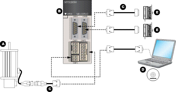
A. MR-J2-JR Servomotors
B. MR-J2-JR Amplifiers
C. Cables
D. Software
E. System Options
MR-J2-JR Servomotors
Servomotor Selection
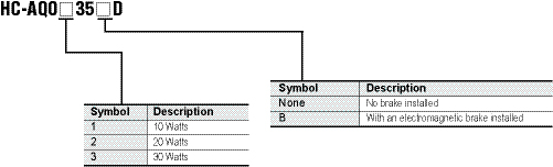
|
Model Number |
HC-AQ0135 |
HC-AQ0235 |
HC-AQ0335 |
||
|
Stocked Item |
- |
- |
S (Non-B only) |
||
|
Continuous Characteristics (*1, *2) |
Rated Output |
kW |
0.01 |
0.02 |
0.03 |
|
Rated Torque |
N•m (oz•in) |
0.0318 (4.503) |
0.0637 (9.021) |
0.0955 (13.524) |
|
|
Rated Speed (*1) |
r/min |
3000 |
|||
|
Maximum Speed |
r/min |
5000 |
4500 |
||
|
Instantaneous Permissible Speed |
r/min |
5750 |
5175 |
||
|
Maximum Torque |
N•m (oz•in) |
0.0955 (13.524) |
0.191 (27.048) |
0.287 (40.643) |
|
|
Power at Continuous Rated Torque |
kW/s |
2.0 |
5.6 |
9.7 |
|
|
Inertia Moment (*4) |
J [x 10⁴ kg•m²] |
0.0050 |
0.0072 |
0.0094 |
|
|
WK² [oz•in²] |
0.027 |
0.039 |
0.051 |
||
|
Recommended Ratio of Load Inertia Moment to Servomotor Shaft Inertia Moment |
30 times or less |
||||
|
Power Supply Capacity |
Refer to “Power supply capacity and generated loss of servo amplifier” in the Servo Amplifier Instruction Manual |
||||
|
Rated Current (Maximum Current) (A) |
2.4 (7.7) |
2.4 (7.7) |
2.3 (7.4) |
||
|
Speed/Position Detector |
Encoder (resolution: 8192 pulses/rev) |
||||
|
Accessory |
Encoder |
||||
|
Insulation Class |
Class B |
||||
|
Structure |
Totally-enclosed self-cooling (protection type: IP55 (*6)) |
||||
|
Environmental Conditions (*5) |
Refer to Section 2.1 in the Servomotor Instruction Manual |
||||
|
Weight kg (lb) (*3) |
0.19 (0.419) |
0.22 (0.485) |
0.25 (0.551) |
||
Notes:
- When the power supply voltage drops, we cannot guarantee the output and rated speed.
- 80% ED at low noise.
80% ED: Indicates the condition in which operation time at read torque accounts for 80% and the other no load time accounts for 20% in a single operation cycle. - When the servomotor is equipped with reduction gear or electromagnetic brake, refer to the corresponding outline dimension drawing. For the EN Standard and UL/cUL Standard compliant models, please contact Mitsubishi.
- If the load inertia moment ratio exceeds the indicated value, please contact Mitsubishi.
- When the equipment is to be used in places where it is subjected to oil and/or water, such as on machine field sites, optional features apply to the equipment.
- Except for the shaft-through portion and connector end.
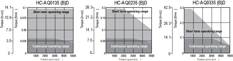
MR-J2-JR Amplifiers
Amplifier Selection
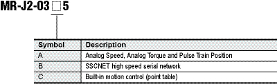
|
Model Number |
MR-J2-03A5 |
MR-J2-03B5 |
MR-J2-03C5 |
|||
|
Stocked Item |
S |
- |
- |
|||
|
Circuit Power Supply (Note) |
Voltage |
21.6 to 30VDC (instantaneous permissible voltage 34V) |
||||
|
Power Supply Capacity |
HC-AQ0135D |
Continuous 0.8A, Max. 2.4A |
||||
|
HC-AQ0235D |
Continuous 1.6A, Max. 4.8A |
|||||
|
HC-AQ0335D |
Continuous 2.4A, Max. 7.2A |
|||||
|
Control Circuit Power Supply (Note) |
24VDC+10% 200mA (400mA when using the servomotor equipped with electromagnetic brake) |
|||||
|
System |
Sine-wave PWM control, current control system |
|||||
|
Dynamic Brake |
Built-in |
|||||
|
Protective Functions |
Overcurrent shut-off, regenerative overvoltage shut-off, overload shut-off, (electronic thermal relay), servomotor overheat protection, encoder fault protection, undervoltage, instantaneous power failure protection, overspeed protection, excessive error protection |
|||||
|
Speed Frequency Response |
250Hz or more |
|||||
|
Structure |
Open (IP00) |
|||||
|
Environment |
Ambient Temperature |
Operation |
°C (°F) |
0 to +55 (non-freezing) (32 to +131 (non-freezing)) |
||
|
Storage |
°C (°F) |
-20 to +65 (non-freezing) (-4 to +149 (non-freezing)) |
||||
|
Ambient Humidity |
Operation (Storage) |
90%RH or less (non-condensing) |
||||
|
Atmosphere |
Indoors (no direct sunlight), Free from corrosive gas, flammable gas, oil mist, dust and dirt |
|||||
|
Altitude |
Max. 1000m (3280 ft) above sea level |
|||||
|
Vibration |
m/s² (ft/s²) |
5.9 or less (19.4 or less) |
||||
|
Weight |
kg (lb) |
0.2 (0.44) |
||||
Note: To comply with the low voltage directive, use a reinforced insulation stabilizing power supply.
Cables
|
Motor Type |
Power/Encoder Cable Length |
Power/Encoder Cable Model Number |
Stocked Item |
|
HC-AQ0135D or HC-AQ0135BD |
2 Meter |
MR-JRCBL2M-H |
S |
|
HC-AQ0135D or HC-AQ0135BD |
5 Meter |
MR-JRCBL5M-H |
- |
|
HC-AQ0135D or HC-AQ0135BD |
10 Meter |
MR-JRCBL10M-H |
- |
|
HC-AQ0235D or HC-AQ0235BD |
2 Meter |
MR-JRCBL2M-H |
S |
|
HC-AQ0235D or HC-AQ0235BD |
5 Meter |
MR-JRCBL5M-H |
- |
|
HC-AQ0235D or HC-AQ0235BD |
10 Meter |
MR-JRCBL10M-H |
- |
|
HC-AQ0335D or HC-AQ0335BD |
2 Meter |
MR-JRCBL2M-H |
S |
|
HC-AQ0335D or HC-AQ0335BD |
5 Meter |
MR-JRCBL5M-H |
- |
|
HC-AQ0335D or HC-AQ0335BD |
10 Meter |
MR-JRCBL10M-H |
- |
Software
|
Description |
Model Number |
Stocked Item |
|
Windows Communication Software |
MR-CONFIGURATOR |
S |
|
Communication Cable |
MR-JRPCATCBL3M |
S |
System Options
|
Description |
Model Number |
Stocked Item |
|
Terminal Block |
MR-TB20 |
S |
|
Terminal Block Cable 0.5 Meter |
MR-J2TBL05M |
S |
|
Terminal Block Cable 1.0 Meter |
MR-J2TBL1M |
S |
|
Encoder Connector Kit (instead of MR-JRCBL_M-H Cable) |
MR-JRCNM |
- |
|
CN1-I/O Connector Kit (contains 2 connectors, one each for CN1A & CN1B) |
MR-J2CN1 |
S |
|
CN1-I/O Pigtail Cables (one each optional for CN1A & CN1B) |
MR-CCN1CBL-3M (3m length) |
S |
Manuals
|
Description |
Model Number |
Stocked Item |
|
MR-J2-03A5 Instruction Manual |
SH(NA)3200 |
MEAU.com |
|
MR-J2-03B5 Instruction Manual |
SH(NA)030005 |
MEAU.com |
|
MR-J2-03C5 Instruction Manual |
SH(NA)3209 |
MEAU.com |
|
Servomotor Instruction Manual |
SH(NA)3181 |
MEAU.com |
Информация MR-JN
Overview and Description
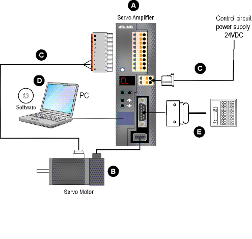
A. MR-JN Rotary Amplifiers
B. MR-JN Super Servomotors
C. Cables and Connectors
D. Software
E. System Options
Servomotor Selection
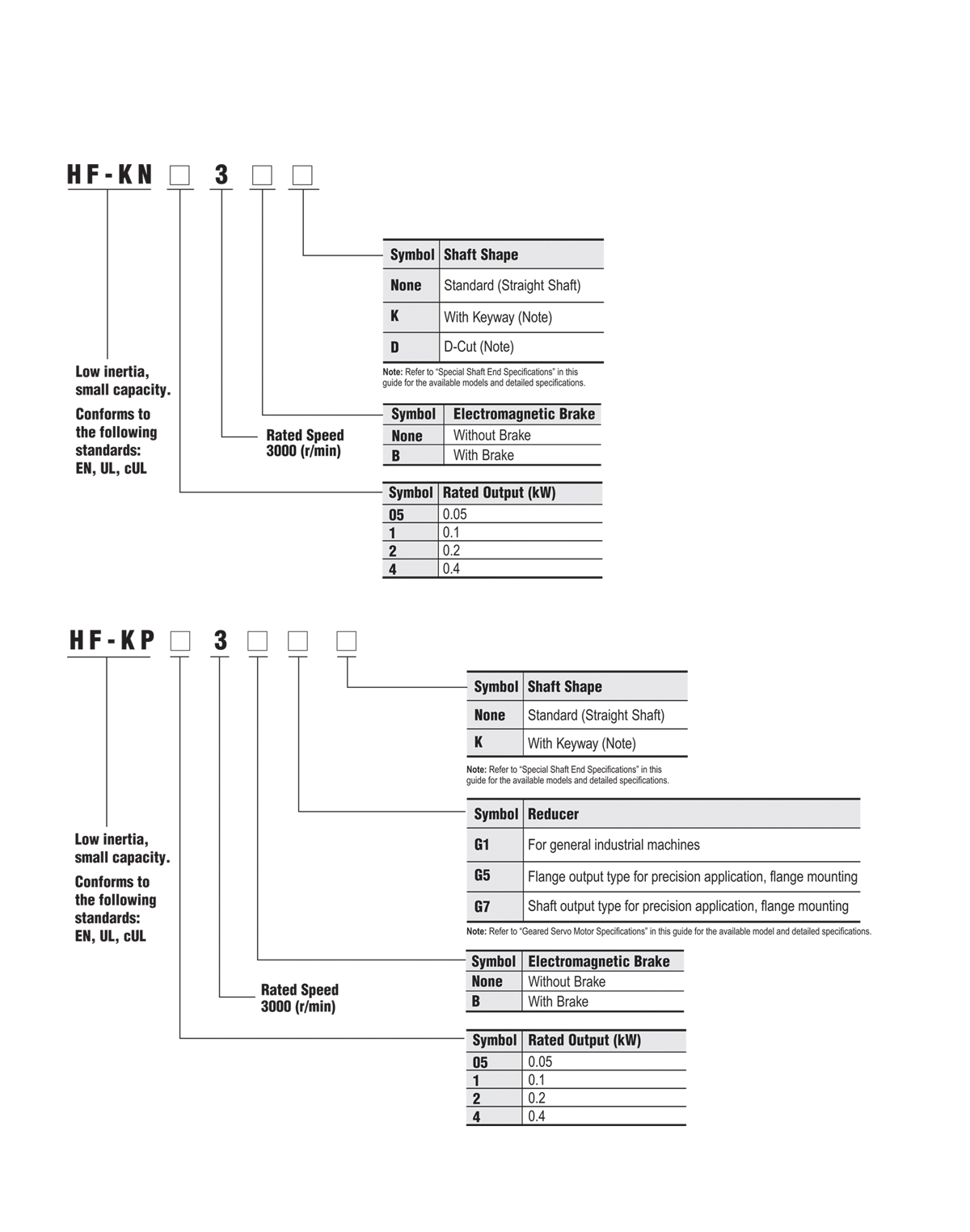
Stocked Motors
|
Model Number |
|
HF-KN053 |
|
HF-KN053B |
|
HF-KN13 |
|
HF-KN13B |
|
HF-KN23K |
|
HF-KN23BK |
|
HF-KN43K |
|
HF-KN43BK |
HF-KN Servomotor Specifications
|
Servomotor Model HF-KN_ |
HF-KN053(B) |
HF-KN13(B) |
HF-KN23(B) |
HF-KN43(B) | |
|
Servo Amplifier Model MR-J3-_-_ |
MR-JN-10A (1) |
MR-JN-20A (1) |
MR-JN-40A | ||
|
Power Supply Capacity (kVA) (*1) |
0.3 |
0.3 |
0.5 |
0.9 | |
|
Continuous Running Duty |
Rated Output (W) |
50 |
100 |
200 |
400 |
|
Rated Torque (N•m [oz•in]) (*8) |
0.16 (22.7) |
0.32 (45.3) |
0.64 (90.6) |
1.3 (184) | |
|
Maximum Torque (N•m [oz•in]) |
0.48 (68.0) |
0.95 (135) |
1.9 (269) |
3.8 (538) | |
|
Rated Speed (r/min) |
3000 | ||||
|
Maximum Speed (r/min) |
4500 | ||||
|
Permissible Instantaneous Speed (r/min) |
5175 | ||||
|
Power Rate Continuous Rated Torque (kW/s) |
4.87 |
11.5 |
16.9 |
38.6 | |
|
Rated Current (A) |
0.9 |
0.8 |
1.4 |
2.7 | |
|
Maximum Current (A) |
2.7 |
2.4 |
4.2 |
8.1 | |
|
Regenerative Braking Freq. (times/min) (*2) |
(*3) |
(*3) |
470 |
261 | |
|
Moment of inertia
|
Standard |
0.052 (0.284) |
0.088 (0.481) |
0.24 (1.31) |
0.42 (2.30) |
|
With Electromagnetic Brake |
0.054 (0.295) |
0.090 (0.492) |
0.31 (1.69) |
0.50 (2.73) | |
|
Recommended Load / Motor Inertia Moment Ratio (*4) |
15 times maximum |
24 times maximum |
22 times maximum | ||
|
Speed/Position Detector |
Incremental 17-bit encoder (resolution: 131072 p/rev) | ||||
|
Insulation Class |
Class B | ||||
|
Structure |
Totally enclosed non-ventilated (protection level: IP65) (*5) | ||||
|
Environment |
Ambient Temperature |
0 to 40°C (32 to 104°F) (non-freezing), storage: -15 to 70°C (5 to 158°F) (non-freezing) | |||
|
Ambient Humidity |
80% RH maximum (non-condensing), storage: 90% RH maximum (non-condensing) | ||||
|
Atmosphere |
Indoors (no direct sunlight); no corrosive gas, inflammable gas, oil mist or dust | ||||
|
Elevation / Vibration (*5) |
1000m or less above sea level X: 49m/s² Y: 49m/s² | ||||
|
Weight kg (lb) |
Standard |
0.4 (0.89) |
0.5 (1.1) |
1.0 (2.2) |
1.4 (3.1) |
|
With Electromagnetic Brake |
0.6 (1.3) |
0.7 (1.5) |
1.4 (3.1) |
1.8 (4.0) | |
Notes:
- The power supply capacity varies depending on the power supply’s impedance.
- The regenerative braking frequency shows the permissible frequency when the motor, without a load and an optional regeneration unit, decelerates from the rated speed to a stop. When a load is connected; however, the value will be the table value/(m+1), where m=load inertia moment/motor inertia moment. When the operating speed exceeds the rated speed, the regenerative braking frequency is inversely proportional to the square of (operating speed/rated speed). If the operating speed changes frequently or when the regeneration is constant (as with vertical feeds), find the regenerative heating value (W) in operation. Provisions must be made to keep this heating value below the tolerable regenerative power (W).Optimal regenerative resistor varies for each system. Select the most suitable regenerative resistor by using the capacity selection software. Refer to the section “Options • Optional regeneration unit” in this catalog for details on the tolerable regenerative power (W).
- When the motor decelerates to a stop from the rated speed, the regenerative frequency will not be limited if the effective torque is within the rated torque range. When the motor decelerates to a stop from the maximum speed, the regenerative frequency will not be limited if the effective torque is within the rated torque range and if the load to motor inertia moment is 8 times or less for HF-KN053(B) or 4 time or less for HF-KN13(B).
- Contact your local sales office if the load to motor inertia moment ratio exceeds the value in the table.
- The shaft-through portion is excluded.
- The vibration direction is shown in the diagram to the right. The value indicates the maximum value of the component (normally the bracket in the opposite direction of the motor shaft). Fretting of the bearing occurs easily when the motor stops, so maintain vibration to approximately one-half of the allowable value.
- In the environment where the servomotor is exposed to oil mist, oil and/or water, a standard specification servomotor may not be usable. Contact your local sales office for more details.
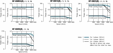
HF-KP Geared Servomotor Specifications
|
Servomotor Model HF-KP_ |
HF-KP053(B)G_ |
HF-KP13(B)G_ |
HF-KP23(B)G_ |
HF-KP43(B)G_ | |
|
Servo Amplifier Model MR-J3-_-_ |
MR-JN-10A (1) |
MR-JN-20A (1) |
MR-JN-40A | ||
|
Power Supply Capacity (kVA) (*1) |
0.3 |
0.3 |
0.5 |
0.9 | |
|
Continuous Running Duty |
Rated Output (W) |
50 |
100 |
200 |
400 |
|
Rated Torque (N•m [oz•in]) (*8) |
0.16 (22.7) |
0.32 (45.3) |
0.64 (90.6) |
1.3 (184) | |
|
Maximum Torque (N•m [oz•in]) |
0.48 (68.0) |
0.95 (135) |
1.9 (269) |
3.8 (538) | |
|
Rated Speed (r/min) |
3000 | ||||
|
Maximum Speed (r/min) |
4500 (*6) | ||||
|
Permissible Speed (r/min) |
Refer to HF-KP Series Geared Servomotor Dimensions in this section | ||||
|
Power Rate Continuous Rated Torque (kW/s) |
4.87 |
11.5 |
16.9 |
38.6 | |
|
Rated Current (A) |
0.9 |
0.8 |
1.4 |
2.7 | |
|
Maximum Current (A) |
2.7 |
2.4 |
4.2 |
8.1 | |
|
Regenerative Braking Freq. (times/min) (*2) |
(*3) |
(*3) |
474 |
276 | |
|
Moment of inertia
|
Standard |
Refer to HF-KP Series Geared Servomotor Dimensions in this section | |||
|
With Electromagnetic Brake | |||||
|
Permissible Load to Motor Inertia Moment Ratio |
Refer to “Geared Servomotor Specifications” in this catalog. | ||||
|
Speed/Position Detector |
Absolute/incremental 18-bit encoder (resolution 262144 p/rev) (*10) | ||||
|
Insulation Class |
Class B | ||||
|
Structure |
Totally enclosed non-ventilated (protection level: IP44) (*4) | ||||
|
Environment |
Ambient Temperature |
0 to 40°C (32 to 104°F) (non-freezing), storage: -15 to 70°C (5 to 158°F) (non-freezing) | |||
|
Ambient Humidity |
80% RH maximum (non-condensing), storage: 90% RH maximum (non-condensing) | ||||
|
Atmosphere |
Indoors (no direct sunlight); no corrosive gas, inflammable gas, oil mist or dust | ||||
|
Elevation / Vibration (*5) |
1000m or less above sea level X: 49m/s² Y: 49m/s² | ||||
|
Weight kg (lb) |
Standard |
Refer to HF-KP Series Geared Servomotor Dimensions in this section | |||
|
With Electromagnetic Brake | |||||
Notes:
- The power supply capacity varies depending on the power supply’s impedance.
- The regenerative braking frequency shows the permissible frequency when the motor, without a load and an optional regeneration unit, decelerates from the rated speed to a stop. When a load is connected; however, the value will be the table value/(m+1), where m=load inertia moment/motor inertia moment. When the operating speed exceeds the rated speed, the regenerative braking frequency is inversely proportional to the square of (operating speed/rated speed). If the operating speed changes frequently or when the regeneration is constant (as with vertical feeds), find the regenerative heating value (W) in operation. Provisions must be made to keep this heating value below the tolerable regenerative power (W).Optimal regenerative resistor varies for each system. Select the most suitable regenerative resistor by using the capacity selection software. Refer to the section “Options • Optional Regeneration Unit” in this catalog for details on the tolerable regenerative power (W).
- When the motor decelerates to a stop from the rated speed, the regenerative frequency will not be limited if the effective torque is within the rated torque range. When the motor decelerates to a stop from the maximum speed, the regenerative frequency will not be limited if the effective torque is within the rated torque range and if the load to motor inertia moment is 8 times or less for HF-KP053(B)G_ or 4 time or less for HF-KP13(B)G_.
- The shaft-through portion is excluded.
- The vibration direction is shown in the diagram to the right. The value indicates the maximum value of the component (normally the bracket in the opposite direction of the motor shaft). Fretting of the bearing occurs easily when the motor stops, so maintain vibration to approximately one-half of the allowable value.
- The values are applicable when combining with MR-JN servo amplifier series.
- In the environment where the servomotor is exposed to oil mist, oil and/or water, a standard specification servomotor may not be usable. Contact your local sales office for more details.
- The values are applicable for the servomotor without reducer.
- The values are applicable at the reducer input shaft.
- When combined with MR-JN servo amplifier series, the detector performance is equivalent to an incremental 17-bit encoder.
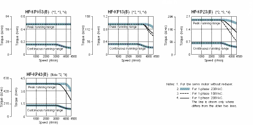
MR-JN Rotary Motor Shaft Details and Servomotor Dimensions
D-Cut Shaft (50W & 100W Motors Only) (*1)
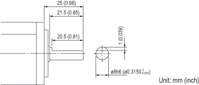
HF-KN Series
Keyway with Key Included (200W, 400W) (*1)
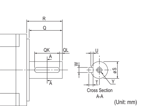
|
Motor Model |
Capacity (W) |
Variable Dimensions | ||||||||
|
T |
S |
R |
Q |
W |
QK |
QL |
U |
Y | ||
|
HF-KN_K |
200, 400 |
5
|
14h6 (0.554) |
30 (1.18) |
27 (1.06) |
5
|
20 (0.79) |
3
|
3
|
M4 Depth 15 (0.59) |
HF-KP Series
Keyway with Key Included (200W, 400W) (*1, 2, 3)
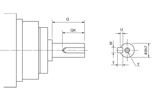
|
Motor Model |
Reduction Ratio |
Variable Dimensions | ||||||
|
S |
Q |
W |
QK |
U |
T |
Y | ||
|
HF-KP053G7K |
1/5 |
16 |
28 |
5 |
25 |
3 |
5 |
M4 Screw Depth 8mm |
|
1/11 | ||||||||
|
1/21 | ||||||||
|
1/33 | ||||||||
|
1/45 | ||||||||
|
HF-KP13G7K |
1/5 | |||||||
|
1/11 | ||||||||
|
1/21 | ||||||||
|
1/33 |
25 |
42 |
8 |
36 |
4 |
7 |
M6 Screw Depth 12mm | |
|
1/45 | ||||||||
|
HF-KP23G7K |
1/5 |
16 |
28 |
5 |
25 |
3 |
5 |
M4 Screw Depth 8mm |
|
1/11 | ||||||||
|
1/21 |
25 |
42 |
8 |
36 |
4 |
7 |
M6 Screw Depth 12mm | |
|
1/33 | ||||||||
|
1/45 | ||||||||
|
HF-KP43G7K |
1/5 |
16 |
28 |
5 |
25 |
3 |
5 |
M4 Screw Depth 8mm |
|
1/11 |
25 |
42 |
8 |
36 |
4 |
7 |
M6 Screw Depth 12mm | |
|
1/21 | ||||||||
|
1/33 |
40 |
82 |
12 |
70 |
5 |
8 |
M10 Screw Depth 20mm | |
|
1/45 | ||||||||
Notes:
- The servomotor with the keyway shaft or the D-cut shaft cannot be used in frequent start/stop applications.
- A key (single-point key) is supplied.
- The dimensions not mentioned in the drawings are the same as those of the straight shaft of HF-KP_G7. Refer to “HF-KP Series Geared Servomotor Dimensions • HF-KP_(B)G7” in this guide.
HF-KN Series
HF-KN053(B), HF-KN13(B)
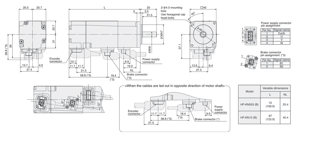
HF-KN23(B), HF-KN43(B)
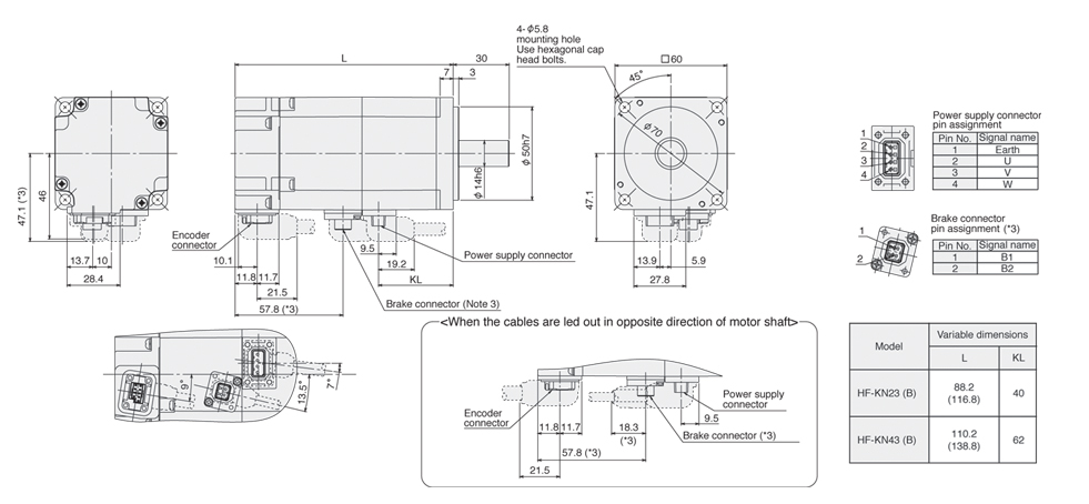
MR-JN Rotary HF-KP Series Geared Servomotor Dimensions
HF-KP_(B)G1
The actual shapes of the mounting screws may differ.
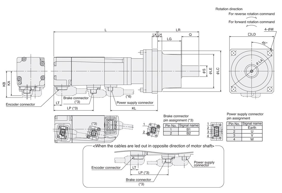
|
Model |
Reduction Ratio (Actual Reduction Ratio) |
Moment of Inertia |
Variable Dimensions |
Weight | ||||||||||||||||||
|
J(x10-4kg•m²) |
J(oz•in²) |
L |
LA |
LC |
LD |
LE |
S |
LH |
LK |
KL |
LG |
Q |
LR |
M |
KA |
KB |
LT |
LP |
kg |
lb | ||
|
HF-KP053(B)G1 |
1/5 (9/44) |
0.089 (0.091) |
0.487 (0.498) |
110.9 (152) |
75 |
60h7 |
65 |
50 |
16h6 |
6.5 |
8 |
69 |
34.5 |
25 |
60.5 |
7 |
36 |
37.1
|
11.7 |
- (58.3) |
1.4 (1.7) |
3.1 (3.8) |
|
1/12 (49/576) |
0.111 (0.113) |
0.607 (0.618) |
128 (170) |
87 |
1.8 (2.1) |
4.0 (4.7) | ||||||||||||||||
|
1/20 (25/484) |
0.093 (0.095) |
0.508 (0.519) | ||||||||||||||||||||
|
HF-KP13(B)G1 |
1/5 (9/44) |
0.125 (0.127) |
0.683 (0.694) |
126.9 (168) |
85 |
1.6 (1.9) |
3.6 (4.2) | |||||||||||||||
|
1/12 (49/576) |
0.147 (0.149) |
0.804 (0.815) |
144.9 (186) |
103 |
2.0 (2.3) |
4.4 (5.1) | ||||||||||||||||
|
1/20 (25/484) |
0.129 (0.131) |
0.705 (0.716) | ||||||||||||||||||||
|
HF-KP23(B)G1 |
1/5 (19/96) |
0.400 (0.470) |
2.19 (2.57) |
130.1 (169.6) |
100 |
82h7 |
90 |
73 |
25h6 |
8 |
10 |
92.8 |
38 |
35 |
74 |
9 |
46 |
47.1 (47.1) |
11.8 |
- (57.8) |
3.3 (3.9) |
7.3 (8.6) |
|
1/12 (25/288) |
0.450 (0.520) |
2.46 (2.84) |
150.1 (189.6) |
112.8 |
3.9 (4.5) |
8.6 (10) | ||||||||||||||||
|
1/20 (253/5000) |
0.420 (0.490) |
2.3 (2.68) | ||||||||||||||||||||
|
HF-KP43(B)G1 |
1/5 (19/96) |
0.570 (0.650) |
3.12 (3.55) |
152 (191.5) |
114.7 |
3.9 (4.4) |
8.6 (9.7) | |||||||||||||||
|
1/12 (25/288) |
0.620 (0.700) |
3.39 (3.83) |
172 (211.5) |
134.7 |
4.5 (5.0) |
10 (11) | ||||||||||||||||
|
1/20 (253/5000) |
0.930 (1.01) |
5.08 (5.52) |
175.5 (215) |
115 |
95h7 |
100 |
86 |
32h6 |
10 |
138.2 |
39 |
50 |
90 |
5.6 (6.1) |
13 (14) | |||||||
Notes:
- Use a friction coupling to fasten a load.
- Dimensions inside ( ) are for the models with electromagnetic brake.
- Only for the models with electromagnetic brake. The electromagnetic brake terminals (B1, B2) do not have polarity.
- The moments of inertia in the table are the values that are converted into motor shaft for the motor with reducer (and with electromagnetic brake).
- For dimensions where there is no tolerance listed, use general tolerance. The actual dimensions may be 1mm to 3mm larger than the dimensions listed since the outer frame of the reducer is made by casting. Design a machine in order to make allowances.
- Lead out the power supply cable in opposite direction of the motor shaft for the following servomotors: All gear ratios for HF-KP053(B)G1 and HF-KP13(B)G1
HF-KP_(B)G5
The actual shapes of the mountig screws may differ.
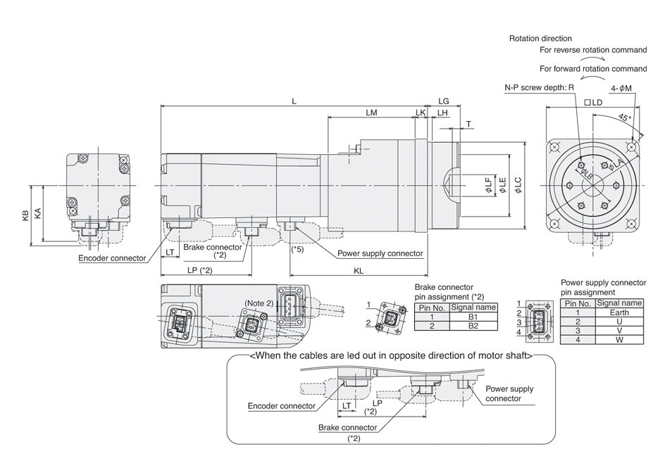
|
Model |
Reduction Ratio (Actual Reduction Ratio) |
Moment of Inertia |
Variable Dimensions |
Weight | ||||||||||||||||||||||
|
J(x10-4kg•m²) |
J(oz•in²) |
L |
LA |
LB |
LC |
LD |
LE |
LF |
LG |
LH |
LK |
LM |
KL |
T |
N |
P |
R |
M |
KA |
KB |
LT |
LP |
kg |
lb | ||
|
HF-KP053(B)G5 (*5) |
1/5 |
0.120 (0.122) |
0.656 (0.667) |
130.4 (171.5) |
70 |
30 |
56h7 |
60 |
40 |
14H7 |
3 |
8 |
56 |
88.5 |
5 |
6 |
M4 |
7 |
5.5 |
36 |
37.1 (38.8) |
11.7 |
-
|
1.1 (1.4) |
2.5 (3.1) | |
|
1/11 |
0.112 (0.114) |
0.612 (0.623) |
1.2 (1.5) |
2.7 (3.3) | ||||||||||||||||||||||
|
1/21 |
0.103 (0.105) |
0.563 (0.574) | ||||||||||||||||||||||||
|
1/33 |
0.097 (0.099) |
0.53 (0.514) | ||||||||||||||||||||||||
|
1/45 |
0.097 (0.099) |
0.53 (0.514) | ||||||||||||||||||||||||
|
HF-KP13(B)G5 (*5) |
1/5 |
0.156 (0.158) |
0.853 (0.864) |
146.4 (187.5) |
104.5 |
1.3 (1.6) |
2.9 (3.6) | |||||||||||||||||||
|
1/11 |
0.148 (0.150) |
0.809 (0.82) |
1.4 (1.7) |
3.1 (3.8) | ||||||||||||||||||||||
|
1/21 |
0.139 (0.141) |
0.76 (0.771) | ||||||||||||||||||||||||
|
1/33 |
0.150 (0.152) |
0.82 (0.831) |
148.9 (190) |
105 |
45 |
85h7 |
90 |
59 |
24H7 |
8 |
10 |
56.5 |
107 |
M6 |
10 |
9 |
2.6 (2.9) |
5.8 (6.4) | ||||||||
|
1/45 |
0.149 (0.151) |
0.815 (0.826) | ||||||||||||||||||||||||
|
HF-KP23(B)G5 (*5) |
1/5 |
0.411 (0.511) |
2.41 (2.79) |
140.6 (180.1) |
70 |
30 |
56h7 |
60 |
40 |
14H7 |
3 |
8 |
56 |
103.3 |
M4 |
7 |
5.5 |
46 |
47.1 (47.1) |
11.8 |
-
|
1.8 (2.4) |
4.0 (5.3) | |||
|
1/11 |
0.443 (0.513) |
2.42 (2.80) |
1.9 (2.5) |
4.2 (5.6) | ||||||||||||||||||||||
|
1/21 |
0.738 (0.808) |
4.03 (4.42) |
147.6 (187.1) |
105 |
45 |
85h7 |
90 |
59 |
24H7 |
8 |
10 |
61 |
110.3 |
M6 |
10 |
9 |
3.4 (4.1) |
7.5 (9.1) | ||||||||
|
1/33 |
0.692 (0.762) |
3.78 (4.17) | ||||||||||||||||||||||||
|
1/45 |
0.691 (0.761) |
3.78 (4.16) | ||||||||||||||||||||||||
|
HF-KP43(B)G5 |
1/5 |
0.621 (0.701) |
3.4 (3.83) |
162.5 (202) |
70 |
30 |
56h7 |
60 |
40 |
14H7 |
3 |
8 |
56 |
125.2 |
M4 |
7 |
5.5 |
2.3 (2.9) |
5.1 (6.4) | |||||||
|
1/11 |
0.996 (1.08) |
5.45 (5.90) |
169.5 (209) |
105 |
45 |
85h7 |
90 |
59 |
24H7 |
8 |
10 |
61 |
132.2 |
M6 |
10 |
9 |
4.0 (4.6) |
8.9 (11) | ||||||||
|
1/21 |
0.918 (0.998) |
5.02 (5.46) | ||||||||||||||||||||||||
|
1/33 |
0.970 (1.05) |
5.3 (5.74) |
181.5 (221) |
135 |
60 |
115h7 |
120 |
84 |
32H7 |
13 |
13 |
70 |
144.2 |
M8 |
12 |
11 |
6.1 (6.7) |
14 (15) | ||||||||
|
1/45 |
0.964 (1.04) |
5.27 (5.69) | ||||||||||||||||||||||||
Notes:
- Dimensions inside ( ) are for the models with electromagnetic brake.
- Only for the models with electromagnetic brake. The electromagnetic brake terminals (B1, B2) do not have polarity.
- The moments of inertia in the table are the values that are converted into motor shaft for the motor with reducer (and with electromagnetic brake).
- For dimensions where there is no tolerance listed, use general tolerance. The actual dimensions may be 1mm to 3mm larger than the dimensions listed since the outer frame of the reducer is made by casting. Design a machine in order to make allowances.
- Lead out the power supply cable in opposite direction of the motor shaft for the following servomotors: All gear ratios for HF-KP053(B)G5 and HF-KP13(B)G5; Gear ratios of 1/21, 1/33 and 1/45 for HF-KP23(B)G5
The actual shapes of the mounting screws may differ.
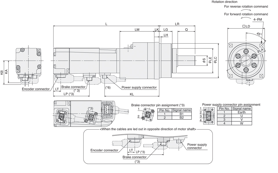
|
Model |
Reduction Ratio (Actual Reduction Ratio) |
Moment of Inertia |
Variable Dimensions |
Weight | |||||||||||||||||||
|
J(x10-4kg•m²) |
J(oz•in²) |
L |
LA |
LC |
LD |
LE |
S |
LG |
LH |
Q |
LR |
LK |
LM |
KL |
M |
KA |
KB |
LT |
LP |
kg |
lb | ||
|
HF-KP053(B)G7 (*6) |
1/5 |
0.126 (0.128) |
0.689 (0.70) |
130.4 (171.5) |
70 |
56h7 |
60 |
40 |
16h7 |
21 |
3 |
28 |
58 |
8 |
56 |
88.5 |
5.5 |
36 |
37.1 (38.8) |
11.7 |
-
|
1.2 (1.5) |
2.7 (3.3) |
|
1/11 |
0.113 (0.115) |
0.618 (0.629) |
1.3 (1.6) |
2.9 (3.6) | |||||||||||||||||||
|
1/21 |
0.103 (0.105) |
0.563 (0.574) | |||||||||||||||||||||
|
1/33 |
0.097 (0.099) |
0.53 (0.514) | |||||||||||||||||||||
|
1/45 |
0.097 (0.099) |
0.53 (0.514) | |||||||||||||||||||||
|
HF-KP13(B)G7 (*6) |
1/5 |
0.162 (0.164) |
0.886 (0.897) |
146.4 (187.5) |
104.5 |
1.4 (1.7) |
3.1 (3.8) | ||||||||||||||||
|
1/11 |
0.149 (0.151) |
0.815 (0.826) |
1.5 (1.8) |
3.3 (4.0) | |||||||||||||||||||
|
1/21 |
0.139 (0.141) |
0.76 (0.771) | |||||||||||||||||||||
|
1/33 |
0.151 (0.153) |
0.826 (0.837) |
148.9 (190) |
105 |
85h7 |
90 |
59 |
25h7 |
27 |
8 |
42 |
80 |
10 |
56.5 |
107 |
9 |
3.0 (3.3) |
6.7 (7.3) | |||||
|
1/45 |
0.149 (0.151) |
0.815 (0.826) | |||||||||||||||||||||
|
HF-KP23(B)G7 (*6) |
1/5 |
0.447 (0.517) |
2.44 (2.83) |
140.6 (180.1) |
70 |
56h7 |
60 |
40 |
16h7 |
21 |
3 |
28 |
58 |
8 |
56 |
103.3 |
5.5 |
46 |
47.1 (47.1) |
11.8 |
-
|
1.9 (2.5) |
4.2 (5.6) |
|
1/11 |
0.443 (0.513) |
2.42 (2.80) |
2.0 (2.6) |
4.4 (5.8) | |||||||||||||||||||
|
1/21 |
0.740 (0.810) |
4.05 (4.43) |
147.6 (187.1) |
105 |
85h7 |
90 |
59 |
25h7 |
27 |
8 |
42 |
80 |
10 |
61 |
110.3 |
9 |
3.8 (4.5) |
8.4 (10) | |||||
|
1/33 |
0.693 (0.763) |
3.79 (4.17) | |||||||||||||||||||||
|
1/45 |
0.691 (0.761) |
3.78 (4.16) | |||||||||||||||||||||
|
HF-KP43(B)G7 |
1/5 |
0.627 (0.707) |
3.43 (3.87) |
162.5 (202) |
70 |
56h7 |
60 |
40 |
16h7 |
21 |
3 |
28 |
58 |
8 |
56 |
125.2 |
5.5 |
2.4 (3.0) |
5.3 (6.7) | ||||
|
1/11 |
1.00 (1.08) |
5.47 (5.90) |
169.5 (209) |
105 |
85h7 |
90 |
59 |
25h7 |
27 |
8 |
42 |
80 |
10 |
61 |
132.2 |
9 |
4.4 (5.0) |
9.7 (11) | |||||
|
1/21 |
0.920 (1.00) |
5.03 (5.47) | |||||||||||||||||||||
|
1/33 |
0.976 (1.06) |
5.3 (5.80) |
181.5 (221) |
135 |
115h7 |
120 |
84 |
40h7 |
35 |
13 |
82 |
133 |
13 |
70 |
144.2 |
11 |
7.5 (8.1) |
17 (18) | |||||
|
1/45 |
0.967 (1.05) |
5.29 (5.74) | |||||||||||||||||||||
Notes:
- Use a friction coupling to fasten a load.
- Dimensions inside ( ) are for the models with electromagnetic brake.
- Only for the models with electromagnetic brake. The electromagnetic brake terminals (B1, B2) do not have polarity.
- The moments of inertia in the table are the values that are converted into motor shaft for the motor with reducer (and with electromagnetic brake).
- For dimensions where there is no tolerance listed, use general tolerance. The actual dimensions may be 1mm to 3mm larger than the dimensions listed since the outer frame of the reducer is made by casting. Design a machine in order to make allowances.
- Lead out the power supply cable in opposite direction of the motor shaft for the following servomotors: All gear ratios for HF-KP053(B)G7 and HF-KP13(B)G7; Gear ratios of 1/21, 1/33 and 1/45 for HF-KP23(B)G7
Amplifier Selection

Servo Amplifier Specifications
|
Servo Amplifier Model |
MR-JN-10A |
MR-JN-20A |
MR-JN-40A |
MR-JN-10A1 |
MR-JN-20A1 | |
|
Stocked Item |
S |
S |
S |
S |
S | |
|
Output |
Rated Voltage |
3-phase 170VAC | ||||
|
Rated Current (A) |
1.1 |
1.6 |
2.8 |
1.1 |
1.6 | |
|
Main Circuit Power Supply |
Voltage/Frequency (*1, *2) |
1-phase 200VAC to 230VAC 50/60Hz |
1-phase 100VAC to 120VAC 50/60Hz | |||
|
Rated Current (A) |
1.5 |
2.4 |
4.5 |
3.0 |
5.0 | |
|
Permissible Voltage Fluctuation |
1-phase 170VAC to 253VAC |
1-phase 85VAC to 132VAC | ||||
|
Permissible Frequency Fluctuation |
±5% maximum | |||||
|
Control Circuit Power Supply |
Voltage |
24VDC | ||||
|
Rated Current (A) |
0.5 | |||||
|
Permissible Voltage Fluctuation |
±10% maximum | |||||
|
Power Consumption (W) |
10 | |||||
|
Interface Power Supply |
24VDC 10% (required current capacity: 0.2A (*5)) | |||||
|
Tolerable regenerative Power of Built-In Regenerative Resistor (W) (*3, *4) |
- |
10 |
10 |
- |
10 | |
|
Control System |
Sine-wave PWM control/current control system | |||||
|
Dynamic Brake |
Built-in (*6) | |||||
|
Safety Features |
Overcurrent shutdown, regeneration overvoltage shutdown, overload shutdown (electronic thermal), servomotor overheat protection, encoder fault protection, regeneration fault protection, undervoltage/sudden power outage protection, overspeed protection, excess error protection | |||||
|
Position Control Mode |
Maximum Input Pulse Frequency |
1Mpps (when using differential receiver), 200kpps (when using open collector) | ||||
|
Positioning Feedback Pulse |
Encoder resolution: 131072 p/rev | |||||
|
Command Pulse Multiple |
Electronic gear A/B multiple, A: 1 to 65535, B: 1 to 65535, 1/50 < A/B < 500 | |||||
|
Positioning Complete Width Setting |
0 to ±65535 pulses (command pulse unit) | |||||
|
Excess Error |
±3 rotations | |||||
|
Torque Limit |
Set by parameters | |||||
|
Internal Speed Control mode |
Speed Control Range |
Internal speed command 1:5000 | ||||
|
Speed Command Input |
Set by parameters | |||||
|
Speed Fluctuation Rate |
±0.01% maximum (load fluctuation 0 to 100%); 0% (power fluctuation ±10%) | |||||
|
Torque Limit |
Set by parameters | |||||
|
Internal Torque Control Mode |
Torque Command Input |
Set by parameters | ||||
|
Speed Limit |
Set by parameters | |||||
|
Positioning Mode (*8) |
Point table method, Program method | |||||
|
Structure |
Self-cooling open (IP20) | |||||
|
Environment |
Ambient Temperature |
0 to 55°C (32 to 131°F) (non-freezing), storage: -20 to 65°C (-4 to 149°F) (non-freezing) | ||||
|
Ambient Humidity |
90% RH maximum (non-condensing), storage: 90% RH maximum (non-condensing) | |||||
|
Atmosphere |
Indoors (no direct sunlight); no corrosive gas, inflammable gas, oil mist or dust | |||||
|
Elevation |
1000m or less above sea level | |||||
|
Vibration |
5.9m/s² or less at 10 to 55Hz (direction of X, Y, and Z axes) | |||||
|
Weight kg (lb) |
0.6 (1.3) |
0.6 (1.3) |
0.7 (1.5) |
0.6 (1.3) |
0.6 (1.3) | |
Note:
- Rated output and speed of a servomotor are applicable when the servo amplifier, combined with the servomotor, is operated within the specified power supply voltage and frequency. Torque drops when the power supply voltage is below the specified value.
- For torque characteristics when combined with a servomotor, refer to “Servomotor Torque Characteristics” in this catalog.
- Optimal regenerative resistor varies for each system. Select the most suitable regenerative resistor by using the capacity selection software.
- Refer to “Options • Optional regeneration unit” in this catalog for the tolerable regenerative power (W).
- 0.2A is the value when all of the input/output points are used. The current capacity can be stepped down according to the number of input/output points in use. Refer to “MR-JN-_A INSTRUCTION MANUAL” for details.
- When using the built-in dynamic brake, refer to “MR-JN-_A INSTRUCTION MANUAL” for the permissible load to motor inertia moment ratio.
- The servo amplifier can be installed closely. In this case, keep the ambient temperature within 0 to 45°C (32 to 113°F), or use the servo amplifier at 75% or less of the effective load rate.
- Servo amplifier with software version B0 or above is required for the positioning function.
HF-JN Cables and Connectors
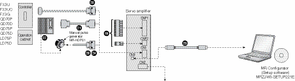
For encoder cable length 10m or shorter
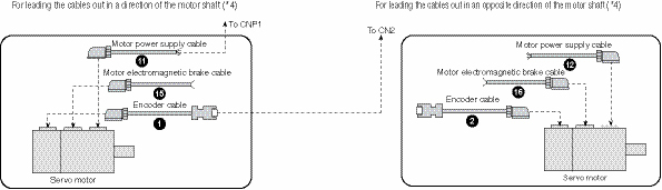
For encoder cable length over 10m
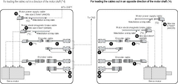
Notes:
- This cable does not have a long bending life, so always fix the cable before using.
- If the length exceeds 10m, relay a cable using MR-PWS2CBL03M-A1-L/-A2-L cable. This cable does not have a long bending life, so always fix the cable before using. Refer to “MR-JN-_A INSTRUCTION MANUAL” for details on manufacturing the relay cable.
- If the length exceeds 10m, relay a cable using MR-BKS2CBL03M-A1-L/-A2-L cable . This cable does not have a long bending life, so always fix the cable before using. Refer to “MR-JN-_A INSTRUCTION MANUAL” for details on manufacturing the relay cable.
- Cables for leading two different directions may be used for one servomotor.
MR-JN Rotary Cables and Connectors (refer to charts above)
Encoder Cables
|
Item |
Model Number
|
Stocked Lengths |
Protection Level |
Diagram | ||
|
|
10m or Shorter (Direct Connection Type) |
Lead Out in Direction of Motor Shaft |
MR-J3ENCBL_M-A1-H
|
2, 5, 10 |
IP65 |
|
|
MR-J3ENCBL_M-A1-L
|
2, 5, 10 |
IP65 | ||||
|
|
Lead Out in Opposite Direction of Motor Shaft |
MR-J3ENCBL_M-A2-H
|
2, 5, 10 |
IP65 | ||
|
MR-J3ENCBL_M-A2-L
|
2, 5, 10 |
IP65 | ||||
|
|
Exceeding 10m (Relay Type) |
Lead Out in Direction of Motor Shaft |
MR-J3JCBL03M-A1-L cable length 0.3 (*1) |
S |
IP20 |
|
|
|
Lead Out in Opposite Direction of Motor Shaft |
MR-J3JCBL03M-A2-L cable length 0.3 (*1) |
S |
IP20 | ||
|
|
Amplifier-Side Cable |
MR-EKCBL_M-H _= 20, 30, 40, or 50 (*1) |
20, 30 |
IP20 |
| |
|
MR-EKCBL_M-L _= 20 or 30 (*1) |
- |
IP20 | ||||
|
|
Junction Connector, Amplifier-Side Connector |
MR-ECNM |
S |
IP20 |
| |
|
|
Motor Side Encoder Cable Lead Out In Direction Of Motor Shaft |
MR-J3JSCBL03M-A1-L Cable length 0.3m
|
S |
IP65 |
Use this in combination of cable numbers 9 or 10 | |
|
|
Motor Side Encoder Cable Lead Out In Opposite Direction Of Motor Shaft |
MR-J3JSCBL03M-A2-L Cable length 0.3m
|
S |
IP67 | ||
|
|
Amplifier-Side Encoder Cable |
MR-J3ENSCBL_M-H _ = cable length 2, 5, 10, 20, 30, 40, 50m (*1) |
2, 5, 10, 20, 30 |
IP67 |
Use this in combination of cable numbers 7 or 8 | |
|
MR-J3ENSCBL_M-L _ = cable length 2, 5, 10, 20, 30m (*1) |
2, 5 |
IP67 | ||||
|
|
Junction Connector Set |
MR-J3SCNS |
S |
IP67 |
| |

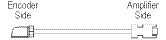


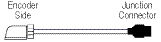


Notes:
- -H and -L indicate bending life. -H indicates a long bending life and -L indicates a standard bending life.
- The IP rating indicated is for the connector’s protection against ingress of dust and water when coupled to a servo amplifier/servomotor. If the IP rating of the servo amplifier/servomotor differs from that of these connectors, overall IP rating depends on the lowest of all.
Motor Power Supply Cables
|
Item |
Model Number
|
Stocked Lengths |
Protection Level |
Diagram | ||
|
|
10m or Shorter (Direct Connection Type) |
Lead Out in Direction of Motor Shaft (Non-shielded) |
MR-PWS1CBL_M-A1-H _= 2, 5 or 10 (*1, *2) |
2, 5, 10 |
IP65 |
|
|
MR-PWS1CBL_M-A1-L _= 2, 5 or 10 (*1, *2) |
2, 5, 10 |
IP65 | ||||
|
Lead Out in Direction of Motor Shaft (Shielded) |
MR-J3PS_M-A1
|
5 |
IP65 | |||
|
|
Lead Out in Opposite Direction of Motor Shaft (Non-shielded) |
MR-PWS1CBL_M-A2-H _= 2, 5 or 10 (*1, *2) |
2, 5, 10 |
IP65 | ||
|
MR-PWS1CBL_M-A2-L _= 2, 5 or 10 (*1, *2) |
2, 5, 10 |
IP65 | ||||
|
Lead Out in Opposite Direction of Motor Shaft (Shielded) |
MR-J3PS_M-A2
|
5, 10 |
IP65 | |||
|
|
Exceeding 10m (Relay Type) |
Lead Out in Direction of Motor Shaft (Non-shielded) |
MR-PWS2CBL03M-A1-L cable length 0.3 (*2) |
S |
IP55 |
|
|
Lead Out in Direction of Motor Shaft (Shielded) |
MR-J3PS03M-A1
|
S |
IP65 | |||
|
|
Lead Out in Opposite Direction of Motor Shaft (Non-shielded) |
MR-PWS2CBL03M-A2-L cable length 0.3 (*2) |
S |
IP55 | ||
|
Lead Out in Opposite Direction of Motor Shaft (Shielded) |
MR-J3PS03M-A2
|
S |
IP65 | |||


Notes:
- Must order separate power connector 27 or 28 to connect to the power cable.
- -H and -L indicate bending life. -H indicates a long bending life and -L indicates a standard bending life.
Motor Brake Cables
|
Item |
Model Number
|
Stocked Lengths |
Protection Level |
Diagram | ||
|
|
10m or Shorter (Direct Connection Type) |
Lead Out in Direction of Motor Shaft |
MR-BKS1CBL_M-A1-H _= 2, 5, or 10 (*1) |
2, 5, 10 |
IP65 |
|
|
MR-BKS1CBL_M-A1-L _= 2, 5, or 10 (*1) |
- |
IP65 | ||||
|
|
Lead Out in Opposite Direction of Motor Shaft |
MR-BKS1CBL_M-A2-H _= 2, 5, or 10 (*1) |
2, 5, 10 |
IP65 | ||
|
MR-BKS1CBL_M-A2-L _= 2, 5, or 10 (*1) |
- |
IP65 | ||||
|
|
Exceeding 10m (Relay Type) |
Lead Out in Direction of Motor Shaft |
MR-BKS2CBL03M-A1-L cable length 0.3 (*1) |
S |
IP55 |
|
|
|
Lead Out in Opposite Direction of Motor Shaft |
MR-BKS2CBL03M-A2-L cable length 0.3 (*1) |
S |
IP55 | ||


Note:
- -H and -L indicate bending life. -H indicates a long bending life and -L indicates a standard bending life.
CNP1 and CNP2 Connectors
|
Item |
Model Number |
Stocked Item |
Protection Level |
Description | |
|
|
CNP1 Connector (Comes with Amplifier) |
N/A (Comes with amplifier) |
- |
- |
|
|
CNP2 Connector (Comes with Amplifier) |
N/A (Comes with amplifier) |
- |
- |
| |


CN1 Connector
|
Item |
Model Number |
Stocked Lengths |
Protection Level |
Description | |
|
|
CN1 Connector Set |
MR-J2CMP2 |
S |
- |
|
|
|
Junction Terminal Block Cable |
MR-TBNATBL_M
|
05, 1 |
- |
|
|
|
Junction Terminal Block |
MR-TB26A |
S |
- |
|


CN3 Connector
|
Item |
Model Number |
Stocked Lengths |
Protection Level |
Description | |
|
|
USB Cable |
MR-J3USBCBL3M (Cable length 3m) |
S |
- |
|


Pigtail Cable for CN1 on Amp
|
Item |
Model Number |
Stocked Lengths |
Protection Level |
Diagram | |
|
|
CN1 Pigtail Cable (26 pin) |
MR-ECN1CBL-3M (Cable length 3m) |
S |
- |
|


CN2 Connector
|
Item |
Model Number |
Stocked Item |
Protection Level |
Diagram | |
|
|
CN2 Connector Only |
MR-J3CN2 |
S |
- |
|


Software
MR Configurator
This software makes it easy to perform setup, tuning, monitor display, diagnostics, reading and writing of parameters, and test operations with a personal computer. User-satisfying functions that enable the balance with the machine system, optimum control and short start up time are available.
- This software can set up and tune your servo system easily with a personal computer.
- Multiple monitor functions. Graphic display functions are provided to display the servomotor status with the input signal triggers, such as the command pulse, droop pulse and speed.
- Test operations with a personal computer. Test operation of the servomotors can be performed with a personal computer using multiple test mode menus.
- Further advanced tuning is possible with the improved advanced functions.
|
Description |
Model Number |
Stocked Item |
|
Windows Communication Software |
MR-CONFIGURATOR |
S |
|
Communication Cable |
MR-J3USBCBL3M |
S |
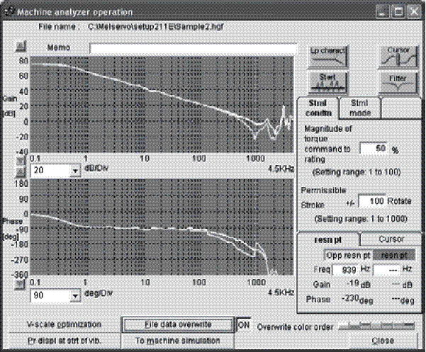
System Options
Manual Pulse Generator
|
Servo Amplifier Type |
Model Number |
Stocked Item |
Description |
|
All MR-JN Models |
MR-HDP01 |
S |
|

Line Noise Filter
|
Servo Amplifier Type |
Model Number |
Stocked Item |
Description |
|
All MR-JN Models |
FR-BSF01 |
S |
|

Radio Noise Filter
|
Servo Amplifier Type |
Model Number |
Stocked Item |
Description |
|
All MR-JN Models |
FR-BIF |
S |
|

Power Factor Improvement AC Reactor
|
Model Number |
Applicable Servo Amplifier |
Stocked Item |
|
MRL-00204 |
MR-JN-10A (1), MR-JN-20A |
- |
|
MRL-00401 |
MR-JN-40A, MR-JN-20A1 |
- |
EMC Filter
|
Servo Amplifier Type |
Model Number |
Stocked Item |
Description |
|
All MR-JN Models |
MF3F480-010.233MF |
- |
|

Note: Contact MEAU for additional filter options.
Optional Regeneration Resistors
|
Servo Amplifier Model |
Tolerable Regenerative Power of Built-in Regenerative Resistor (W) |
Tolerable Regenerative Power of Optional Regeneration Unit (W) | |
|
MR-RB032 (40Ω) |
MR-RB12 (40Ω) | ||
|
Stocked Item |
- |
S |
S |
|
MR-JN-10A (*1) |
- |
30 |
- |
|
MR-JN-20A (*1) |
10 |
30 |
100 |
|
MR-JN-40A |
10 |
30 |
100 |
Note:
- The power values in this table are resistor-generated powers, not rated powers.
Информация MR-J3 Direct Drive Motors
Overview and Configuration
MR-J3 Direct Drive Servomotors and Amplifiers
Direct drive motor is newly added to the MELSERVO-J3 Series. Direct drive arrangement with the motor provides higher rigidity. In addition, the high-resolution encoder with the motor enables high accuracy control. The motor’s low profile design contributes to compact construction and a low center of gravity for enhanced machine stability. This motor is suitable for rotation and index tables used in semiconductor manufacturing, liquid crystal manufacturing and machine tool devices. The direct drive motor and servo amplifier will be compatible with global standards (EN, UL and cUL standards).
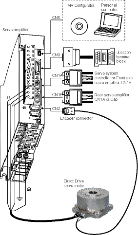
Note:
Please consult product marketing for all direct drive motor opportunities.
A. MR-J3-Direct Drive Amplifiers
B. MR-J3-Direct Drive Servomotors
C. Cables
D. Software and Manuals
E. System Options
MR-J3-Direct Drive Amplifiers
Amplifier Selection
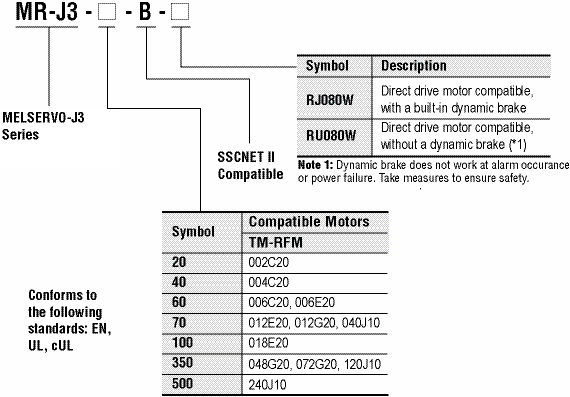
Amplifier Specifications
|
MR-J3-_-RJ080W |
20B |
40B |
60B |
70B |
100B |
350B |
500B |
|
|
Main Circuit Power Supply |
Voltage / Frequency (*1,* 2) |
3-phase 200 to 230VAC 50/60Hz or 1-phase 200 to 230VAC 50/60Hz |
3-phase 200 to 230VAC 50/60Hz |
|||||
|
Permissible Voltage Fluctuation |
For 3-phase 200 to 230VAC: 3-phase 170 to 253VAC For 1-phase 200 to 230VAC: 1-phase 170 to 253VAC |
3-phase 170 to 253VAC |
||||||
|
Permissible Frequency Fluctuation |
±5% maximum |
|||||||
|
Control Circuit Power Supply |
Voltage / Frequency |
1-phase 200 to 230VAC 50/60Hz |
||||||
|
Permissible Voltage Fluctuation |
1-phase 170 to 253VAC |
|||||||
|
Permissible Frequency Fluctuation |
±5% maximum |
|||||||
|
Power Consumption (W) |
30 |
45 |
||||||
|
Interface Power Supply |
24VDC±10% (required current capacity: 0.15A (*3)) |
|||||||
|
Control System |
Sine-wave PWM control/current control system |
|||||||
|
Dynamic Brake |
Built-in (*4, *5) |
|||||||
|
Safety Features |
Overcurrent shutdown, regeneration overvoltage shutdown, overload shutdown (electronic thermal), |
|||||||
|
Structure |
Natural-cooling, open (IP00) |
Fan-cooling, open (IP00) |
||||||
|
Environment |
Ambient Temperature (*6) |
0 to 55°C (32 to 131°F) (non freezing), storage: -20 to 65°C (-4 to 149°F) (non freezing) |
||||||
|
Ambient Humidity |
90% RH maximum (non condensing), storage: 90% RH maximum (non condensing) |
|||||||
|
Atmosphere |
Indoors (no direct sunlight); no corrosive gas, inflammable gas, oil mist or dust |
|||||||
|
Elevation |
1000m or less above sea level |
|||||||
|
Vibration |
5.9m/s² or less at 10 to 55Hz (directions of X, Y and Z axes) |
|||||||
|
Weight kg (lb) |
0.8 (1.8) |
1.0 (2.2) |
1.0 (2.2) |
1.4 (3.1) |
1.4 (3.1) |
2.3 (5.1) |
4.6 (10) |
|
Notes:
- Rated output and speed of a direct drive motor are applicable when the servo amplifier, combined with the direct drive motor, is operated within the specified power supply voltage and frequency. Torque drops when the power supply voltage is below the specified value.
- Special specification servo amplifiers without a dynamic brake are also available: MR-J3-_B-RU080W. When using the servo amplifier without a dynamic brake, the direct drive motor does not stop immediately at alarm occurrence or power failure. Take measures to ensure safety in the entire system.
- The following servo amplifiers can be mounted closely: MR-J3-20B-RJ080W, -40B-RJ080W, -60B-RJ080W, -70B-RJ080W, -100B-RJ080W and -350B-RJ080W. In this case, operate them at the ambient temperature of 0 to 45°C (32 to 113°F) or at 75% or less of the effective load ratio.
MR-J3-Direct Drive Servomotors
Motor Selection
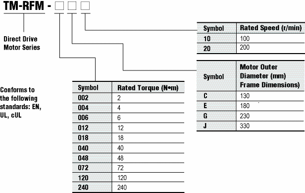
Direct Drive Servomotor Specifications
|
Direct Drive Motor Model TM-RFM |
002C20 |
004C20 |
006C20 |
006E20 |
012E20 |
018E20 |
|
|
Compatible Servo Amplifiers |
20B |
40B |
60B |
60B |
70B |
100B |
|
|
Motor Outer Diameter (Frame Dimensions) (mm) |
ø130 |
ø180 |
|||||
|
Power Supply Capacity (kVA) (*1) |
0.25 |
0.38 |
0.53 |
0.46 |
0.81 |
1.3 |
|
|
Continuous Running Duty |
Rated Output (W) |
42 |
84 |
126 |
126 |
251 |
377 |
|
Rated Torque (N·m [oz·in]) |
2 (283) |
4 (566) |
6 (850) |
6 (850) |
12 (1700) |
18 (2550) |
|
|
Maximum Torque (N·m [oz·in]) |
6 (850) |
12 (1700) |
18 (2550) |
18 (2550) |
36 (5100) |
54 (7650) |
|
|
Rated Speed (r/min) |
200 |
||||||
|
Maximum Speed (r/min) |
500 |
||||||
|
Permissible Instantaneous Speed (r/min) |
575 |
||||||
|
Power Rate at Continuous Rated Torque (kW/s) |
3.7 |
9.6 |
16.1 |
4.9 |
12.9 |
21.8 |
|
|
Rated Current (A) |
1.3 |
2.1 |
3.1 |
3.1 |
3.8 |
5.9 |
|
|
Maximum Current (A) |
3.9 |
6.3 |
9.3 |
9.3 |
12 |
18 |
|
|
Regenerative Braking Frequency (*2) (times/min) |
No limit |
4600 |
2600 |
510 |
560 |
400 |
|
|
Moment of Inertia J (x10-4 kg•m²) [J (oz•in²)] |
10.9 (59.6) |
16.6 (90.8) |
22.4 (122) |
74.0 (405) |
111 (607) |
149 (815) |
|
|
Recommended Load to Motor Inertia Moment Ratio (*3) |
Maximum of 50 times |
||||||
|
Absolute Accuracy (s) |
±15 |
±12.5 |
|||||
|
Encoder Resolution |
1048576p/rev (Absolute/incremental encoder) (*4) |
||||||
|
Insulation Class |
Class F |
||||||
|
Structure |
Totally enclosed non ventilated (IP rating: IP42) (*5) |
||||||
|
Rotor Permissible Load (*8) |
Moment Load (N·m [oz·in]) |
22.5 (3190) |
70 (9910) |
||||
|
Axial Load (N) |
1100 |
3300 |
|||||
|
Environment (*7) |
Ambient Temperature |
0 to 40°C (32 to 104°F) (non freezing), storage: -15 to 70°C (5 to 158°F) (non freezing) |
|||||
|
Ambient Humidity |
80% RH maximum (non condensing), storage: 90% RH maximum (non condensing) |
||||||
|
Atmosphere |
Indoors (no direct sunlight); no corrosive gas, inflammable gas, oil mist, dust or splash of oil or water |
||||||
|
Elevation |
1000m or less above sea level |
||||||
|
Vibration (*6) |
X: 49m/s² Y: 49m/s² |
||||||
|
Weight (kg [lb]) |
5.2 (12) |
6.8 (15) |
8.4 (19) |
11 (25) |
15 (33) |
18 (40) |
|
Notes:
- The power supply capacity varies depending on the power supply’s impedance.
- Contact your local sales office if the load to motor inertia moment ratio exceeds the value in the table.
- Connectors and gap between rotor and stator are excluded.
- In the environment where the direct drive motor is exposed to oil mist, oil and/or water, a standard specification direct drive motor may not be usable. Contact your local sales office for more details.
- The following is calculation examples of axial and moment loads to the rotor (output shaft). The axial and moment loads must be maintained equal to or below the permissible value.
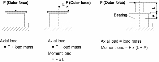
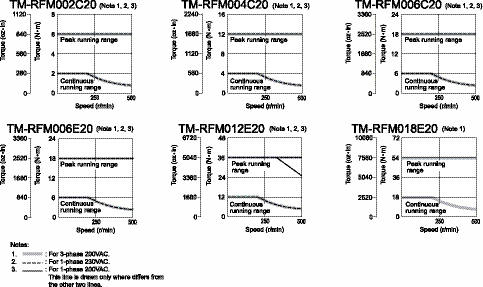
|
Motor outer diameter (mm) (Frame dimensions) |
Dimension A (mm) |
|
Ø130 |
19.1 |
|
Ø180 |
20.2 |
The machine accuracy related to the direct drive motor’s rotor (output shaft and instillation is indicated below.)
|
Item |
Measured Part |
Accuracy (mm) |
|
Runout of flange surface about rotor (output shaft) |
a |
0.05 |
|
Runout of fitting outer diameter of flange surface |
b |
0.07 |
|
Runout of rotor (output shaft) |
c |
0.04 |
|
Runout of rotor (output shaft) end |
d |
0.02 |
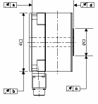
Servomotor Specifications
|
Direct Drive Motor Model TM-RFM |
012G20 |
048G20 |
072G20 |
040J10 |
120J10 |
240J10 |
|
|
Compatible Servo Amplifiers |
70B |
350B |
70B |
350B |
500B |
||
|
Motor Outer Diameter (Frame Dimensions) (mm) |
Ø230 |
Ø330 |
|||||
|
Power Supply Capacity (kVA) (*1) |
0.71 |
2.7 |
3.8 |
1.2 |
3.4 |
6.6 |
|
|
Continuous Running Duty |
Rated Output (W) |
251 |
1005 |
1508 |
419 |
1257 |
2513 |
|
Rated Torque (N·m [oz·in]) |
12 (1700) |
48 (6800) |
72 (10200 |
40 (5660) |
120 (17000) |
240 (34000) |
|
|
Maximum Torque (N·m [oz·in]) |
36 (5100) |
144 (20400) |
216 (30600) |
120 (17000) |
360 (51000) |
720 (102000) |
|
|
Rated Speed (r/min) |
200 |
100 |
|||||
|
Maximum Speed (r/min) |
500 |
200 |
|||||
|
Permissible Instantaneous Speed (r/min) |
575 |
230 |
|||||
|
Power Rate at Continuous Rated Torque (kW/s) |
6.0 |
37.5 |
59.3 |
9.4 |
40.9 |
91.4 |
|
|
Rated Current (A) |
3.4 |
10.9 |
16 |
4.3 |
11 |
20 |
|
|
Maximum Current (A) |
10 |
33 |
48 |
13 |
33 |
60 |
|
|
Regenerative Braking Frequency (*2) (times/min) |
200 |
350 |
250 |
120 |
70 |
40 |
|
|
Moment of Inertia J (x10-4 kg•m²) [J (oz•in²)] |
238 (1300) |
615 (3360) |
875 (4780) |
1694 (9260) |
3519 (19200) |
6303 (34500) |
|
|
Recommended Load to Motor Inertia Moment Ratio (*3) |
Maximum of 50 times |
||||||
|
Absolute Accuracy (s) |
±12.5 |
±10 |
|||||
|
Encoder Resolution |
1048576p/rev (Absolute/incremental encoder) (*4) |
||||||
|
Insulation Class |
Class F |
||||||
|
Structure |
Totally enclosed non ventilated (IP rating: IP42) (*5) |
||||||
|
Rotor Permissible Load (*8) |
Moment Load (N·m [oz·in]) |
93 (13200) |
350 (49600) |
||||
|
Axial Load (N) |
5500 |
16000 |
|||||
|
Environment (*7) |
Ambient Temperature |
0 to 40°C (32 to 104°F) (non freezing), storage: -15 to 70°C (5 to 158°F) (non freezing) |
|||||
|
Ambient Humidity |
80% RH maximum (non condensing), storage: 90% RH maximum (non condensing) |
||||||
|
Atmosphere |
Indoors (no direct sunlight); no corrosive gas, inflammable gas, oil mist, dust or splash of oil or water |
||||||
|
Elevation |
1000m or less above sea level |
||||||
|
Vibration (*6) |
X: 49m/s² Y: 49m/s² |
X: 24.5m/s² Y: 24.5m/s² |
|||||
|
Weight (kg [lb]) |
17 (38) |
36 (80) |
52 (115) |
53 (120) |
91 (205) |
146 (325) |
|
Notes:
- The power supply capacity varies depending on the power supply’s impedance.
- Contact your local sales office if the load to motor inertia moment ratio exceeds the value in the table.
- Connectors and gap between rotor and stator are excluded.
- In the environment where the direct drive motor is exposed to oil mist, oil and/or water, a standard specification direct drive motor may not be usable. Contact your local sales office for more details.
- The following is calculation examples of axial and moment loads to the rotor (output shaft). The axial and moment loads must be maintained equal to or below the permissible value.

|
Motor outer diameter (mm) (Frame dimensions) |
Dimension A (mm) |
|
Ø230 |
24.4 |
|
Ø330 |
32.5 |
Direct Drive Motor Machine Accuracy
The machine accuracy related to the direct drive motor’s rotor (output shaft and instillation is indicated below.)
|
Item |
Measured Part |
Accuracy (mm) |
|
Runout of flange surface about rotor (output shaft) |
a |
0.05 |
|
Runout of fitting outer diameter of flange surface |
b |
0.07 |
|
Runout of rotor (output shaft) |
c |
0.04 |
|
Runout of rotor (output shaft) end |
d |
0.02 |
TM-RFM002C20, TM-RFM004C20, TM-RFM006C20
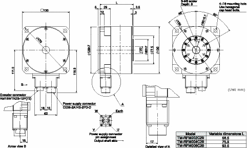
TM-RFM006E20, TM-RFM012E20, TM-RFM018E20
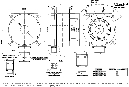
TM-RFM002C20, TM-RFM004C20, TM-RFM006C20
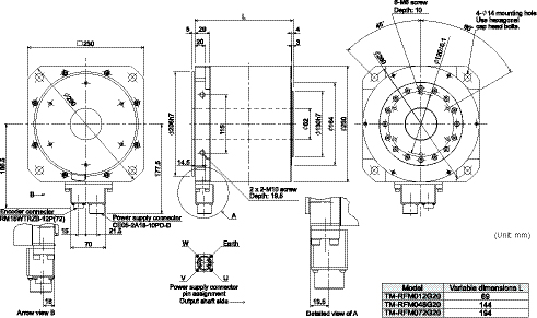
TM-RFM040J10, TM-RFM120J10, TM-RFM240J10
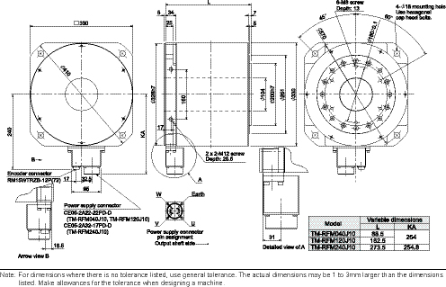
Cables
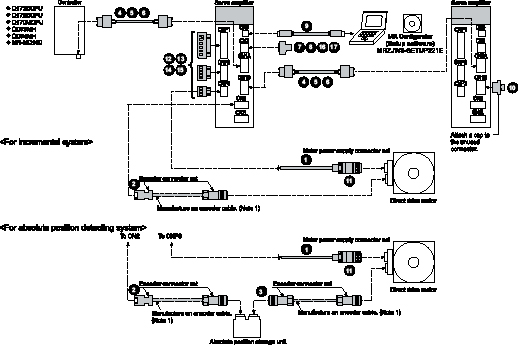
Cables
|
Item |
Motor Model Number |
Cable Number (_ = cable length 2, 5, 10, 15, 20, 25, 30 meter) |
Stocked Lengths (m) |
Protection Level |
Description |
||
|
Power Cables for TM-RFM Series Direct Drive Motors |
|
Standard-Flex, Unshielded Type Cables (straight Type Connector Only) |
TM-RFM002C20 |
MR7S-_M |
2, 5, 10 |
IP65 |
|
|
TM-RFM004C20 |
|||||||
|
TM-RFM006C20 |
|||||||
|
TM-RFM006E20 |
MR7S-_M |
2, 5, 10 |
|||||
|
TM-RFM012E20 |
|||||||
|
TM-RFM018E20 |
|||||||
|
TM-RFM012G20 |
MR-J3P1-_M |
2, 5, 10, 20, 30 |
|||||
|
TM-RFM048G20 |
MR-J3P3-_M |
||||||
|
TM-RFM072G20 |
|||||||
|
TM-RFM040J10 |
MR-J3P4-_M |
2, 5, 10, 20, 30 |
|||||
|
TM-RFM120J10 |
|||||||
|
TM-RFM240J10 |
MR-J3P7-_M |
||||||
|
High-Flex, Shielded Type Cables (straight Type Connector Only) |
TM-RFM002C20 |
MR7S-SH-_M |
- |
IP65 |
|
||
|
TM-RFM004C20 |
|||||||
|
TM-RFM006C20 |
|||||||
|
TM-RFM006E20 |
MR7S-SH-_M |
- |
|||||
|
TM-RFM012E20 |
|||||||
|
TM-RFM018E20 |
|||||||
|
TM-RFM012G20 |
MR-J3PWS1-_M |
2, 5, 10, 15, 20, 30 |
IP67 |
||||
|
TM-RFM048G20 |
MR-J3PWS3-_M |
||||||
|
TM-RFM072G20 |
|||||||
|
TM-RFM040J10 |
MR-J3PWS4-_M |
||||||
|
TM-RFM120J10 |
|||||||
|
TM-RFM240J10 |
MR-J3PWS7-_M |
||||||


Cables continued
|
Model |
Stocked Lengths (M) |
IP Rating (*5) |
Description |
|||
|
For Encoder |
|
Encoder Connector Cable (for connecting servo amplifier and direct drive motor, or for connecting servo amplifier and absolute position storage unit) |
MR-J3DDCNSCBL-_M (_ = cable length 2, 5, 10, 20, 25, 30) |
2, 5, 10, 20 |
IP67 |
|
|
|
Encoder Connector Cable (for connecting absolute position storage unit and direct drive motor) |
MR-J3DDSPSCBL-_M (_= cable length 03, 05, 1, 3) |
03, 05, 1, 3 |
IP67 |
|
|
|
For Controller, CN1A, CN1B |
|
SSCNET III Cable (*1) (Standard Cord for Inside Panel) |
MR-J3BUS_M (_ = cable length: 015, 03, 05, 1, 3m) |
015, 03, 05, 1, 3 |
- |
|
|
|
SSCNET III Cable (*1) (Standard Cable for Outside Panel) |
MR-J3BUS_M-A (_ = cable length: 5, 10, 20m) |
5, 10, 20 |
- |
||
|
|
SSCNET III Cable (*1) (Long Distance Cable, Long Bending Life) |
MR-J3BUS_M-B (_ = cable length: 30, 40, 50m) (*2) |
30 |
- |
|
|
|
For CN3 |
|
CN20 or CN3 Pigtail Cable (20 Pin) |
MR-CCN1CBL-_M (_ = cable length 3, 5m) |
3, 5 |
- |
|
|
For CN3 |
|
Input/Output Signal Connector Set |
MR-J2CN1 |
S |
- |
|
|
For CN5 |
|
Personal Computer Communication Cable - USB |
MR-J3USBCBL3M Cable length: 3m |
S |
- |
|
|
For CN1B |
|
Connector Cap for SSCNET III |
(Standard accessory) |
- |
- |
|
|
For Motor Power Supply |
|
Power Supply Connector Set for TM-RFM_C20, TM-RFM_E20 |
MR-PWCNF (straight type) |
S |
IP67 |
|
|
Power Supply Connector set for TM-RFM_G20 |
MR-PWCNS4 (straight type) |
S |
IP67 |
|
||
|
Power Supply Connector Set for TM-RFM040J10, TM-RFM120J10 |
MR-PWCNS5 (straight type) |
S |
IP67 |
|
||
|
Power Supply Connector Set for TM-RFM240J10 |
MR-PWCNS3 (straight type) |
S |
IP67 |
|
||
|
Power Connectors (Comes with J3 Amplifier standard) |
|
CNP1 Connector 1kW or Less (200VAC) |
54928-0670 |
S |
- |
|
|
CNP1 Connector 2kW - 3.5kW (200VAC) (*6) |
PC4/6-STF-7.62 |
S |
- |
|||
|
|
CNP2 Connector up to 3.5kW (200VAC) (*6) |
54927-0510 |
S |
- |
|
|
|
|
CNP3 Connector 1kW or Less (200VAC) |
54928-0370 |
S |
- |
|
|
|
CNP3 Connector 2kW - 3.5kW (200VAC) (*6) |
PC4/3-STF-7.62 |
S |
- |
|||
|
|
CNP1-2-3 Insertion Tool (200VAC) |
54932-0000 |
S |
- |
|
|
|
For CN3 |
|
20 Pin Terminal Block For J3-B (TB20 Cannot be Used) |
PS7DW-20V14B-F |
S |
- |
|
|
|
Cable for PS7DW-20V14B-F Terminal Block |
MR-J2HBUS_M (_ = Cable length 0.5, 1, 3, 5m) |
05, 1, 3, 5 |
- |
|
|
|
For Encoder |
|
Encoder Connector Set (for connecting servo amplifier and direct drive motor, or for connecting servo amplifier and absolute position storage unit) |
MR-J3DDCNS |
S |
IP67 |
|
|
|
Encoder Connector Set (for connecting absolute position storage unit and direct drive motor) |
MR-J3DDSPS |
S |
IP67 |
|
|


Notes:
- Look carefully through the precautions enclosed with the options before use.
- Contact your local sales office for the cables with ultra-long bending life and/or for unlisted lengths.
- Special tools are required. Contact your local sales office for details.
- The connector and shell kit are soldered type. Models for press bonding type are 10120-6000EL (connector) and 10320-3210-000 (shell kit).
- The IP rating indicated is for the connector’s protection against ingress of dust and water when coupled to a servo amplifier/direct drive motor. If the IP rating of the servo amplifier/direct drive motor differs from that of these connectors, overall IP rating depends on the lowest of all.
Use this model for amplifiers manufactured prior to January 2008.
Software and Manuals
MR-CONFIGURATOR2 • (MRZJW3-MOTSZ111E)
This software makes it easy to perform setup, tuning, monitor display, diagnostics, reading and writing of parameters, and test operations with a personal computer. User-satisfying functions that enable the balance with the machine system, optimum control and short start up time are available.
- This software can set up and tune your servo system easily with a personal computer.
- Multiple monitor functions. Graphic display functions are provided to display the servomotor status with the input signal triggers, such as the command pulse, droop pulse and speed.
- Test operations with a personal computer. Test operation of the servomotors can be performed with a personal computer using multiple test mode menus.
- Further advanced tuning is possible with the improved advanced functions.
Manuals
|
Hardware Description |
Model Number |
Stocked Item |
|
MR-J3-B-RJ080W |
- |
MEAU.com |

|
Description |
Model Number |
Stocked Item |
|
Windows Communication Software |
MR-CONFIGURATOR2 |
S |
|
Communication Cable |
MR-J3USBCBL3M |
S |
System Options
RS-422 Distributor (For Multidrop)
|
Servo Amplifier Type |
Model Number |
Stocked Item |
Description |
|
MR-J3-B |
BMJ-8 |
S |
|

Line Noise Filter
|
Servo Amplifier Type |
Model Number |
Stocked Item |
Description |
|
MR-J3-200B |
FR-BSF01 |
S |
|
|
MR-J3-350B or Larger |
FR-BLF |
S |

EMC Filter
|
Servo Amplifier Type |
Model Number |
Stocked Item |
Description |
|
MR-J3-100B and less |
MF3F480-010.233MF |
- |
|
|
MR-J3-200B ~ 350B |
MF3F480-015.230MF3 |
- |
Note: Contact MEAU for additional filter opportunities.
20 Pin Terminal Block (*1)
|
Servo Amplifier Type |
Model Number |
Stocked Item |
Description |
|
MR-J3-B |
PS7DW-20V14B-F |
S |
|

Note: MR-TB20 terminal block cannot be used for MR-J3-B.
Radio Noise Filter
|
Servo Amplifier Type |
Model Number |
Stocked Item |
Description |
|
All 200VAC J3 Models |
FR-BIF |
S |
|

Battery
|
Model Number |
Description |
Stocked Item |
Description |
|
MR-J3BAT |
The servomotor’s absolute value can be maintained by installing the battery in the servo amplifier. The battery is not required when the servo system is used in an incremental mode. |
S |
|
Absolute Position Storage Unit
|
Model Number |
Description |
|
|
MR-BTAS01 |
Ambient Temperature |
0 to 55°C (32 to 131°F) Non-freezing), |
|
Ambient Humidity |
90% RH max. non-condensing) |
|
|
Atmosphere |
Indoors (no direct sunlight): no corrosive gas, inflammable gas, oil mist, dust or splash of |
|
|
Elevation |
1000m or less above sea level |
|
|
Vibration |
When mounted on the surface AL 49m/s2 or less (direction of X, Y and Z axes) |
|
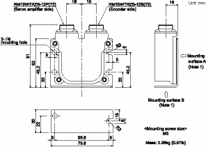
Optional Regeneration Resistors
|
Servo Amplifier |
Built-in Regenerative Resistor/(*1) |
Tolerable Regenerative Power (W) (*3) |
||||||
|
Optional Regeneration Unit (*1) |
||||||||
|
MR-RB032 (40Ω) |
MR-RB12 (40Ω) |
MR-RB30 (13Ω) |
MR-RB31 (6.7Ω) |
MR-RB32 (40Ω) |
MR-RB50 (13Ω)(*2) |
MR-RB51 (6Ω) (*2) |
||
|
Stocked Item |
- |
S |
S |
S |
- |
S |
S |
S |
|
MR-J3-20B-RJ080W |
10 |
30 |
100 |
- |
- |
- |
- |
- |
|
MR-J3-40B-RJ080W |
10 |
30 |
100 |
- |
- |
- |
- |
- |
|
MR-J3-60B-RJ080W |
10 |
30 |
100 |
- |
- |
- |
- |
- |
|
MR-J3-70B-RJ080W |
20 |
30 |
100 |
- |
- |
300 |
- |
- |
|
MR-J3-100B-RJ080W |
20 |
30 |
100 |
- |
- |
300 |
- |
- |
|
MR-J3-350B-RJ080W |
100 |
- |
- |
300 |
- |
- |
500 |
- |
|
MR-J3-500B-RJ080W |
130 |
- |
- |
- |
300 |
- |
- |
500 |
Notes:
- For external dimensions and connections of the built-in regenerative resistor and optional regeneration unit, refer to MELSERVO-J3 catalog.
- Be sure to install a cooling fan. The cooling fan must be supplied by user.
- The power values in this table are resistor-regenerated powers, not rated powers.
Характеристики MXZ-8B140/160
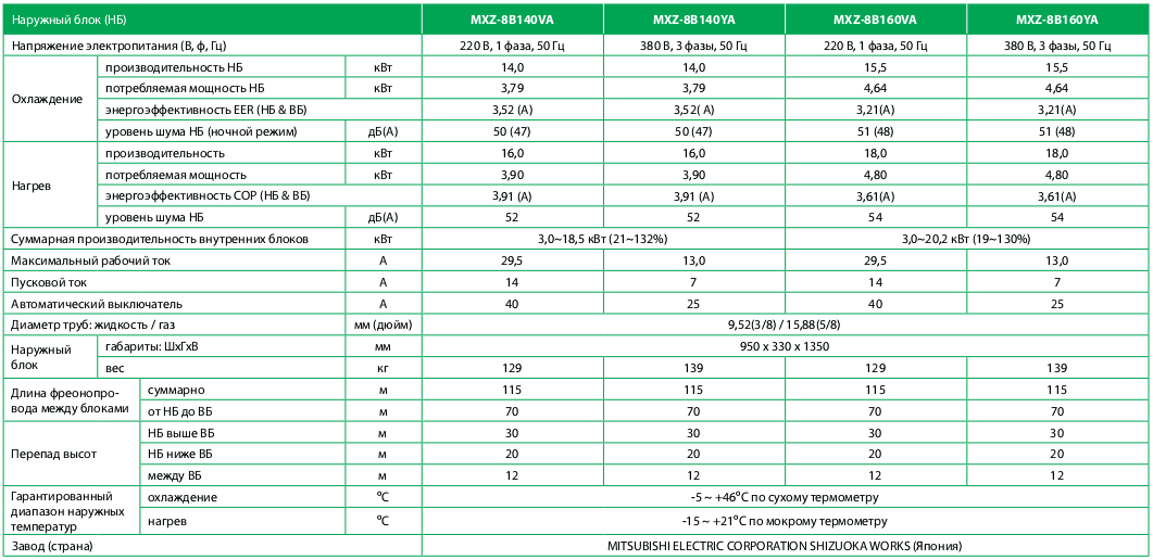
Примечания:
- Указанная в таблице потребляемая мощность относится только к наружному блоку и не учитывает электропотребление внутренних приборов.
- Значения коэффициентов энергоэффективности измерены в следующих системах:
MXZ-8B140VA/YA= MSZ-GE22VAx 8 PAC-AK52BC+ PAC-AK31BC
MXZ-8B160VA/YA= MSZ-GE25VAx 8 PAC-AK52BC+ PAC-AK31BC
Характеристики MXZ-2D/3D/4D/5D/6C
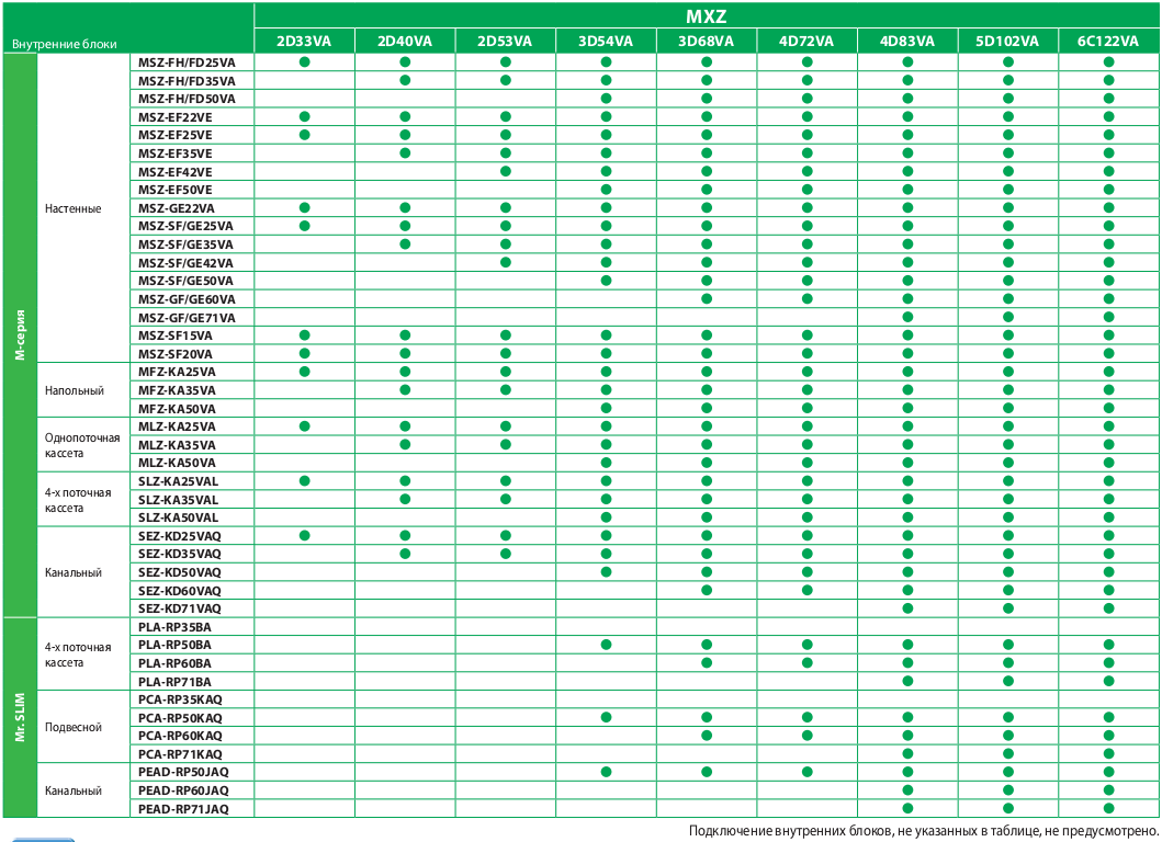
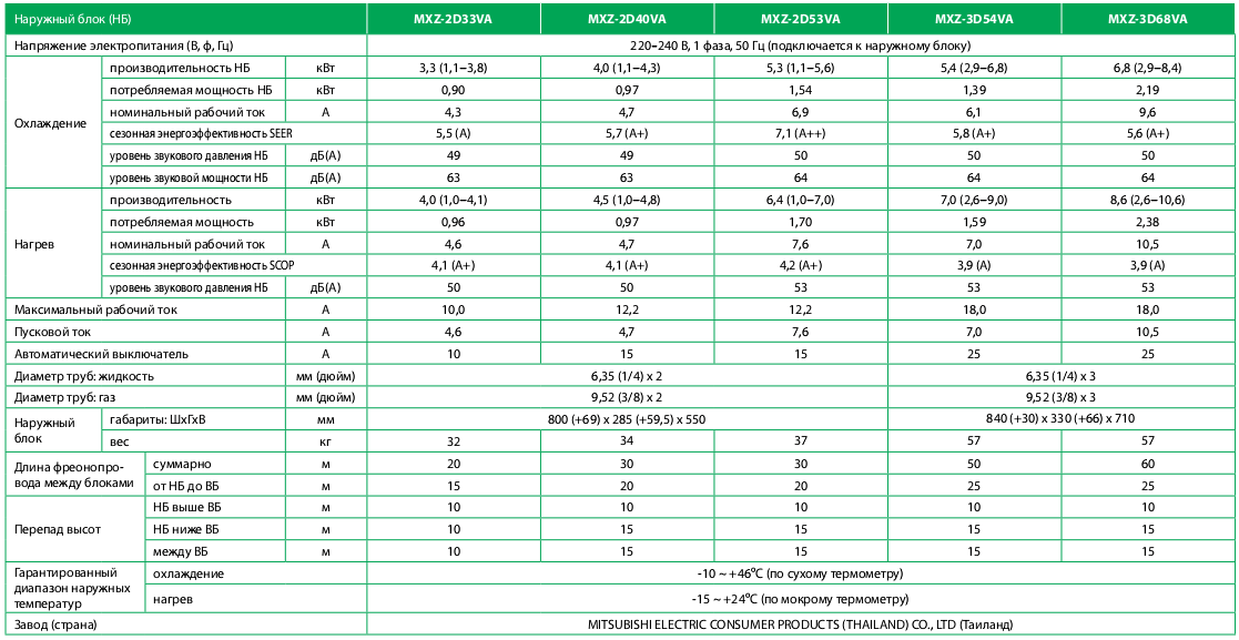
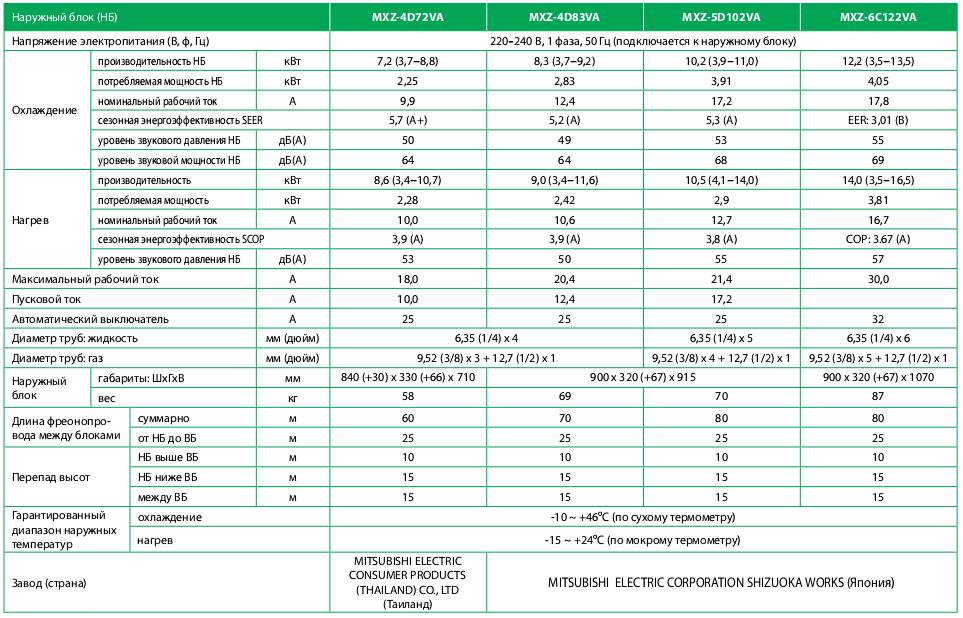
Примечания:
- Указанная в таблице потребляемая мощность относится только к наружному блоку и не учитывает электропотребление внутренних приборов.
- Значения коэффициентов энергоэффективности измерены в следующих системах:
MXZ-2D33VA — MSZ-SF15VA+ MSZ-EF18VE;
MXZ-2D40VA — MSZ-EF18VE + MSZ-EF22VE;
MXZ-2D53VA — MSZ-EF18VE + MSZ-EF35VE;
MXZ-3D54VA — MSZ-EF18VE + MSZ-EF18VE + MSZ-EF18VE;
MXZ-3D68VA — MSZ-EF18VE + MSZ-EF25VE + MSZ-EF25VE;
MXZ-4D72VA — MSZ-EF18VE + MSZ-EF18VE + MSZ-EF18VE + MSZ-EF18VE;
MXZ-4D83VA — MSZ-EF18VE + MSZ-EF18VE + MSZ-EF22VE + MSZ-EF25VE;
MXZ-5D102VA — MSZ-EF18VE + MSZ-EF18VE + MSZ-EF22VE + MSZ-EF22VE + MSZ-EF22VE;
MXZ-6C122VA — MSZ-EF25VE ×6. - Энергетические характеристики системы при подключении других комбинаций внутренних блоков представлены на сайте www.mitsubishi-aircon.ru в разделе «Продукция/Каталог оборудования/Бытовые мультисистемы»