Compatible Linear Encoders (*1, *2)
Информация MR-J3 Linear
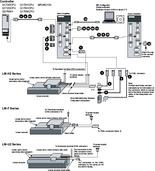
Overview and Configuration
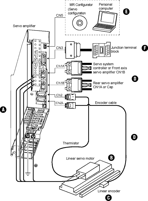
Note:
Please consult product marketing for all linear amplifier and motor opportunities.
A. MR-J3 Linear Amplifiers 350
B. MR-J3 Linear Servomotors 352
C. Linear Encoder 358
D. MR-J3-Linear Cables and Connectors 359
E. Software and Manuals 361
F. Optional Accessories 361
MR-J3 Linear Amplifiers
Amplifier Selection (*1)
Combination of Linear Servomotor and Servo Amplifier
|
Linear Servomotor |
Servo Amplifier | |||
|
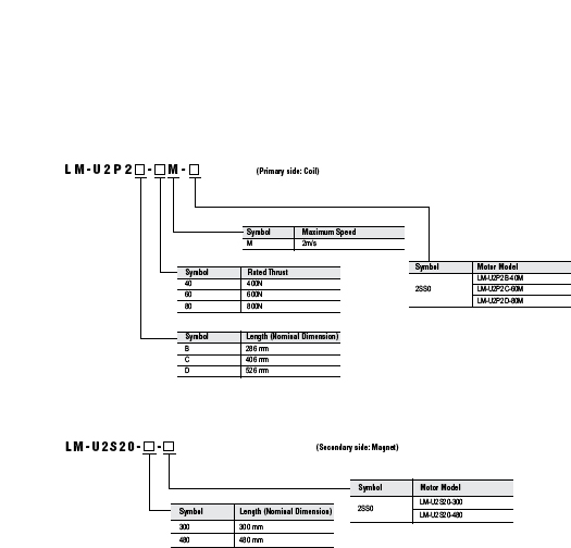
Primary Side (Coil) |
Stocked Item |
Secondary Side (Magnet) | ||
|
LM-H2 Series |
LM-H2P1A-06M-4SS0 |
- |
LM-H2S10-288-4SS0, LM-H2S10-384-4SS0, LM-H2S10-480-4SS0, LM-H2S10-768-4SS0 |
MR-J340BRJ004U500 |
|
LM-H2P2A-12M-1SS0 |
- |
LM-H2S20-288-1SS0, LM-H2S20-384-1SS0, LM-H2S20-480-1SS0, LM-H2S20-768-1SS0 |
MR-J340BRJ004U501 | |
|
LM-H2P2B-24M-1SS0 |
- |
MR-J370BRJ004U502 | ||
|
LM-H2P2C-36M-1SS0 |
- |
MR-J3200BRJ004U503 | ||
|
LM-H2P2D-48M-1SS0 |
- |
MR-J3200BRJ004U504 | ||
|
LM-H2P3A-24M-1SS0 |
- |
LM-H2S30-288-1SS0, LM-H2S30-384-1SS0, LM-H2S30-480-1SS0, LM-H2S30-768-1SS0 |
MR-J370BRJ004U505 | |
|
LM-H2P3B-48M-1SS0 |
- |
MR-J3200BRJ004U506 | ||
|
LM-H2P3C-72M-1SS0 |
- |
MR-J3350BRJ004U507 | ||
|
LM-H2P3D-96M-1SS0 |
- |
MR-J3500BRJ004U508 | ||
|
LM-F Series |
LM-FP2B-06M-1SS0 |
- |
LM-FS20-480-1SS0, LM-FS20-576-1SS0 |
MR-J3200BRJ004U518 (for self-cooling)
|
|
LM-FP2D-12M-1SS0 |
- |
MR-J3500BRJ004U520 (for self-cooling)
| ||
|
LM-FP2F-18M-1SS0 |
- |
MR-J3700BRJ004U522 (for self-cooling)
| ||
|
LM-FP4B-12M-1SS0 |
- |
LM-FS40-480-1SS0, LM-FS40-576-1SS0 |
MR-J3500BRJ004U524 (for self-cooling)
| |
|
LM-FP4D-24M-1SS0 |
- |
MR-J3700BRJ004U526 (for self-cooling
| ||
|
LM-FP4F-36M-1SS0 |
- |
MR-J311KBRJ004U528 (for self-cooling)
| ||
|
LM-FP4H-48M-1SS0 |
- |
MR-J315KBRJ004U530 (for self-cooling)
| ||
|
LM-FP5H-60M-1SS0 |
- |
LM-FS50-480-1SS0, LM-FS50-576-1SS0 |
MRJ322KB4RJ004U532 (for self-cooling) (*1)
| |
|
LM-U2 Series |
LM-U2PAB-05M-0SS0 |
- |
LM-U2SA0-240-0SS0, LM-U2SA0-300-0SS0, LM-U2SA0-420-0SS0 |
MR-J320BRJ004U512 |
|
LM-U2PAD-10M-0SS0 |
- |
MR-J340BRJ004U513 | ||
|
LM-U2PAF-15M-0SS0 |
- |
MR-J340BRJ004U514 | ||
|
LM-U2PBB-07M-1SS0 |
- |
LM-U2SB0-240-1SS0, LM-U2SB0-300-1SS0, LM-U2SB0-420-1SS0 |
MR-J320BRJ004U515 | |
|
LM-U2PBD-15M-1SS0 |
- |
MR-J360BRJ004U516 | ||
|
LM-U2PBF-22M-1SS0 |
- |
MR-J370BRJ004U517 | ||
|
LM-U2P2B-40M-2SS0 |
- |
LM-U2S20-300-2SS0, LM-U2S20-480-2SS0 |
MR-J3200BRJ004U509 | |
|
LM-U2P2C-60M-2SS0 |
- |
MR-J3350BRJ004U510 | ||
|
LM-U2P2D-80M-2SS0 |
- |
MR-J3500BRJ004U511 | ||
Note 1: Servo amplifiers MR-J3-22KB4-RJ004U_, are rated 400VAC. 200VAC class is not available.
Note:
Please consult product marketing for all linear amplifier and motor opportunities.
Amplifier Specifications
|
Servo Amplifier Model
|
20B- RJ004U_ |
40B- RJ004U_ |
60B- RJ004U_ |
70B- RJ004U_ |
200B- RJ004U_ |
350B- RJ004U_ |
500B- RJ004U_ |
700B- RJ004U_ |
11KB- RJ004U_ |
15KB- RJ004U_ |
22KB4-RJ004U_ | ||
|
Main Circuit Power Supply |
Voltage/Frequency (*1) |
3-phase 200 to 230VAC 50/60Hz or
|
3-phase 200 to 230VAC 50/60Hz |
3-phase 380 to 480VAC 50/650/60Hz | |||||||||
|
Permissible Voltage Fluctuation |
For 3-phase 200 to 230VAC: 3-phase 170 to 253VAC For 1-phase 200 to 230VAC: 1-phase 170 to 253VAC |
3-phase 170 to 253VAC |
3-phase 323 to 528VAC | ||||||||||
|
Permissible Frequency Fluctuation |
±5% maximum | ||||||||||||
|
Control Circuit Power Supply |
Voltage/Frequency |
1-phase 200 to 230VAC 50/60Hz |
1-phase 380 to 480VAC 50/60Hz | ||||||||||
|
Permissible Voltage Fluctuation |
1-phase 170 to 253VAC |
1-phase 323 to 528VAC | |||||||||||
|
Permissible Frequency Fluctuation |
±5% maximum | ||||||||||||
|
Power Consumption (W) |
30 |
45 | |||||||||||
|
Interface Power Supply |
24VDC ±10% (required current capacity: 150mA (*3)) | ||||||||||||
|
Linear Encoder Interface |
Serial Interface |
Mitsubishi high-speed serial communication | |||||||||||
|
Pulse Train Interface |
Input Signal |
ABZ phase differential input signal | |||||||||||
|
Minimum Phase Difference |
200ns | ||||||||||||
|
Regenerative Resistor / Tolerable Regenerative Power (W)
|
Built-In Regenerative Resistor |
10 |
10 |
10 |
20 |
100 |
100 |
130 |
170 |
- |
- |
- | |
|
External Regenerative Resistor (*6) |
- |
- |
- |
- |
- |
- |
- |
- |
500
|
850
|
850
| ||
|
Control System |
Sine-wave PWM control/current control system | ||||||||||||
|
Dynamic Brake |
Built-in |
External option | |||||||||||
|
Safety Features |
Overcurrent shutdown, regeneration overvoltage shutdown, overload shutdown (electronic thermal), servomotor overheat protection, encoder fault protection, regeneration fault protection, undervoltage/sudden power outage protection, overspeed protection, excess error protection | ||||||||||||
|
Structure |
Self-cooling open (IP00) |
Fan cooling open (IP00) | |||||||||||
|
Environment |
Ambient Temperature (*2) |
0 to 55°C (32 to 131°F) (non-freezing), storage: -20 to 65°C (-4 to 149°F) (non-freezing) | |||||||||||
|
Ambient Humidity |
90% RH maximum (non condensing), storage: 90% RH maximum (non condensing) | ||||||||||||
|
Atmosphere |
Indoors (no direct sunlight); no corrosive gas, inflammable gas, oil mist or dust | ||||||||||||
|
Elevation |
1000m or less above sea level | ||||||||||||
|
Vibration |
5.9m/s² maximum | ||||||||||||
|
Weight kg (lb) |
0.8 (1.8) |
1.0 (2.2) |
1.0 (2.2) |
1.4 (3.1) |
2.3 (5.1) |
2.3 (5.1) |
4.6 (10) |
6.2 (14) |
18 (40) |
18 (40) |
19 (42) | ||
Notes:
- Rated thrust and speed of a linear servomotor are applicable when the servo amplifier, combined with the linear servomotor, is operated within the specified power supply voltage and frequency. Thrust drops when the power supply voltage is below the specified value.
- The MR-J3-350B-RJ004U_ or smaller servo amplifier can be installed closely. In this case, keep the ambient temperature within 0 to 45°C (32 to 113°F), or use them with 75% or less of the effective load rate.
- 150mA is the value when all of the input/output points are used. The current capacity can be stepped down according to the number of input/output points in use.
- Optimal regenerative resistor varies for each system.
- Refer to the section “Selecting linear servo 3. Selecting optional regenerative unit” in this catalog for the tolerable regenerative power (W).
- The value applies when the external regenerative resistors, GRZG400-MW, (standard accessory) are used with cooling fans (2 units of 92x92mm, minimum air flow: 1.0m3/min). Note that change in the parameter No. PA02 is required.
Electrical wires, circuit breakers, magnetic contactors (example of selection)
The following are examples of wire sizes when 600V polyvinyl chloride insulated wires with a length of 30m are used.
|
Servo Amplifier |
Circuit Breaker |
Magnetic Contactor |
Electrical Wire Size (mm²) | ||||
|
L1, L2, L3 |
L11, L21 |
U, V, W |
P, C |
THM1, THM2 | |||
|
MR-J3-20B-RJ004U_ |
30A frame 5A |
S-N10 |
2 (AWG14) |
1.25 (AWG16) |
1.25 (AWG16 |
2 (AWG14) |
0.2 (AWG24) |
|
MR-J3-40B-RJ004U_ |
30A frame 10A | ||||||
|
MR-J3-60B-RJ004U_ |
30A frame 15A | ||||||
|
MR-J3-70B-RJ004U_ | |||||||
|
MR-J3-200B-RJ004U_ |
30A frame 20A |
S-N18 |
2 (AWG14) | ||||
|
MR-J3-350B-RJ004U_ |
30A frame 30A |
S-N20 |
3.5 (AWG12) |
3.5 (AWG12) | |||
|
MR-J3-500B-RJ004U_ (*1) |
50A frame 50A |
S-N35 |
5.5 (AWG10) |
5.5 (AWG10) | |||
|
MR-J3-700B-RJ004U_ (*1) |
100A frame 75A |
S-N50 |
8 (AWG8) |
8 (AWG8) |
3.5 (AWG12) | ||
|
MR-J3-11KB-RJ004U_ (*1) |
100A frame 100A |
S-N65 |
14 (AWG6) |
22 (AWG4) |
5.5 (AWG10) | ||
|
MR-J3-15KB-RJ004U_ (*1) |
225A frame 125A |
S-N95 |
22 (AWG4) |
30 (AWG2) | |||
|
MR-J3-22KB4-RJ004U_ (*1) |
225A frame 125A |
S-N65 |
14 (AWG6) |
22 (AWG4) | |||
Note:
- When connecting the wires to the terminal screws, be sure to use the screws attached to the terminal blocks.
MR-J3 Linear Servomotors
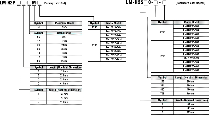
LM-H2 Linear Servomotor Selection
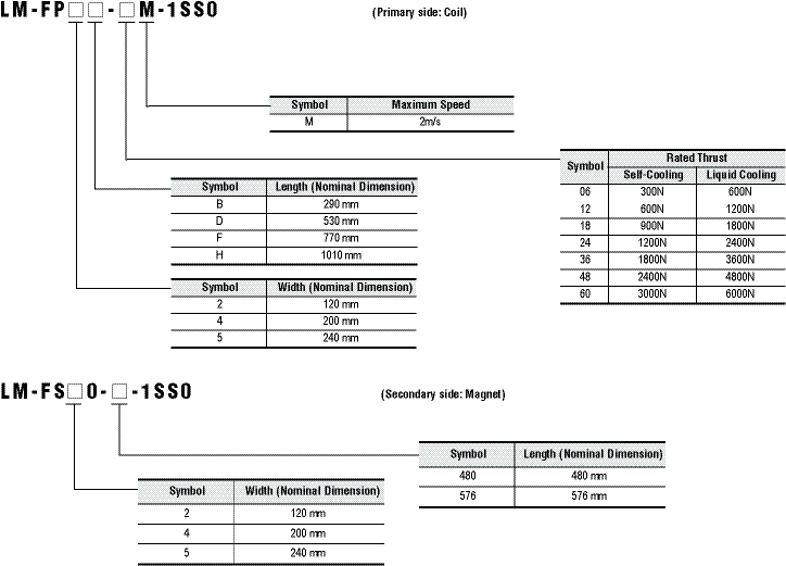
LM-F Linear Servomotor Selection
LM-U2 (Medium Thrust) Linear Servomotor Selection
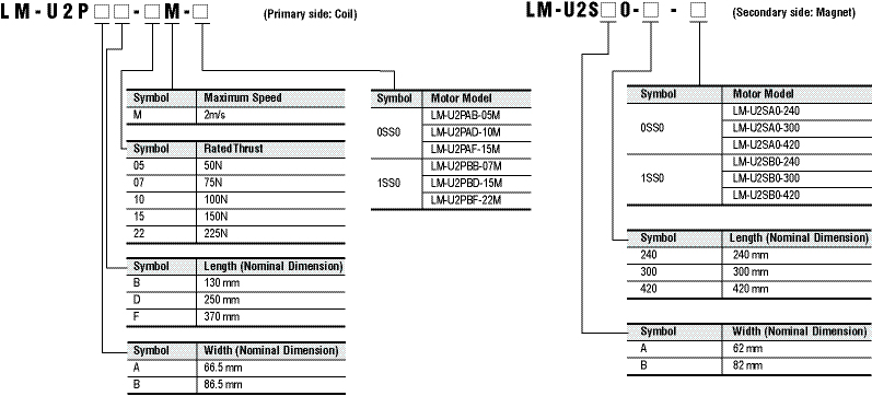
LM-U2 (Large Thrust) Linear Servomotor Selection
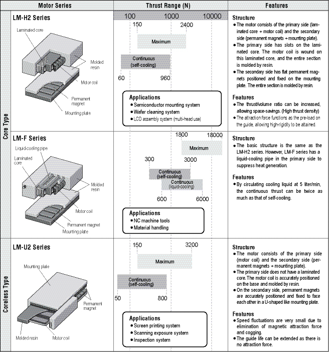
Servomotor Types
LM-H2 Linear Motor Specifications
|
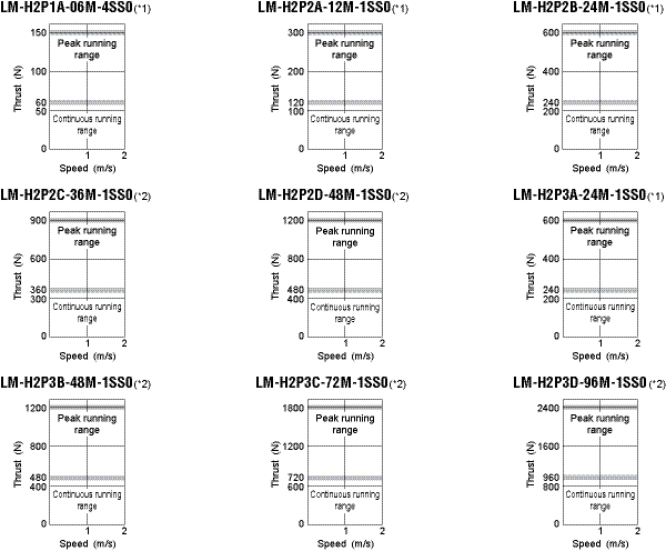
Linear Servomotor Model LM-H2 |
P1A-06M-4SS0 |
P2A-12M-1SS0 |
P2B-24M-1SS0 |
P2C-36M-1SS0 |
P2D-48M-1SS0 |
P3A-24M-1SS0 |
P3B-48M-1SS0 |
P3C-72M-1SS0 |
P3D-96M-1SS0 | |
|
Compatible Amplifier Model MR-J3- |
40B-
|
40B-
|
70B-
|
200B-
|
200B-
|
70B-
|
200B-
|
350B-
|
500B-
| |
|
Power Facility Capacity (kVA) |
0.9 |
0.9 |
1.3 |
3.5 |
3.5 |
1.3 |
3.5 |
5.5 |
7.5 | |
|
Cooling Method |
Self-cooling | |||||||||
|
Thrust |
Continuous (N) |
60 |
120 |
240 |
360 |
480 |
240 |
480 |
720 |
960 |
|
Maximum (N) |
150 |
300 |
600 |
900 |
1200 |
600 |
1200 |
1800 |
2400 | |
|
Maximum Speed (m/s) (*1) |
2.0 | |||||||||
|
Magnetic Attraction Force (N) |
500 |
1000 |
1900 |
2700 |
3500 |
2000 |
3700 |
5300 |
7000 | |
|
Weight kg (lb) |
Primary Side (Coil) |
0.9 (2.0) |
1.4 (3.1) |
2.5 (5.6) |
3.6 (8.0) |
4.7 (11) |
2.4 (5.3) |
4.3 (9.5) |
6.2 (14) |
8.1 (18) |
|
Secondary Side (Magnet) |
288mm / piece: 0.6 (1.4)
|
288mm / piece: 1.1 (2.5)
|
288mm / piece: 3.2 (7.1)
| |||||||
|
Secondary Side Model LM-H2 |
S10-_-4SS0 |
S20-_-1S20 |
S30-_-1SS0 | |||||||
|
Recommended Load / Motor Mass Ratio |
Maximum of 30 times the mass of the linear servomotor’s primary side | |||||||||
|
Structure |
Open (protection level: IP00) | |||||||||
|
Environment |
Ambient Temperature |
0 to 40°C (32 to 104°F) (non-freezing), storage: -15 to 70°C (5 to 158°F) (non-freezing) | ||||||||
|
Ambient Humidity |
80% RH maximum (non-condensing), storage: 90% RH maximum (non-condensing) | |||||||||
|
Atmosphere |
Indoors (no direct sunlight); no corrosive gas, inflammable gas, oil mist or dust | |||||||||
|
Vibration |
49m/s² maximum | |||||||||
|
Elevation |
1000m or less above sea level | |||||||||
Notes: 1. The linear servomotor’s maximum speed or linear encoder’s rated speed, whichever is smaller, is the upper limit value of the linear servomotor’s speed.
Notes:
- For 3-phase 200VAC or 1-phase 200VAC.
- For 3-phase 200VAC.
LM-F Series Linear Motor Specifications
|
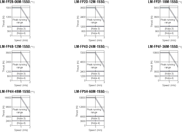
Linear Servomotor Model LM-F |
P2B-06M-1SS0 |
P2D-12M-1SS0 |
P2F-18M-1SS0 |
P4B-12M-1SS0 |
P4D-24M-1SS0 |
P4F-36M-1SS0 |
P4H-48M-1SS0 |
P5H-60M-1SS0 (*2) | |
|
Compatible Amplifier MR-J3 |
Self-Cooling |
200BRJ004U518 |
500BRJ004U520 |
700BRJ004U522 |
500BRJ004U524 |
700BRJ004U526 |
11KBRJ004U528 |
15KBRJ004U530 |
22KB4RJ004U532 |
|
Liquid-Cooling |
200BRJ004U519 |
500BRJ004U521 |
700BRJ004U523 |
500BRJ004U525 |
700B-RJ004U527 |
11KBRJ004U529 |
15KBRJ004U531 |
22KB4RJ004U533 | |
|
Power Facility Capacity (kVA) |
3.5 |
5.5 |
10 |
7.5 |
18 |
18 |
18 |
22 | |
|
Cooling Method |
Self-cooling or liquid-cooling | ||||||||
|
Thrust |
Continuous (Self-Cooling) (N) |
300 |
600 |
900 |
600 |
1200 |
1800 |
2400 |
3000 |
|
Continuous (Liquid-Cooling) (N) |
600 |
1200 |
1800 |
1200 |
2400 |
3600 |
4800 |
6000 | |
|
Maximum (N) |
1800 |
3600 |
5400 |
3600 |
7200 |
10800 |
14400 |
18000 | |
|
Maximum Speed (m/s) (*1) |
2.0 | ||||||||
|
Magnetic Attraction Force (N) |
4500 |
9000 |
13500 |
9000 |
18000 |
27000 |
36000 |
45000 | |
|
Weight kg (lb) |
Primary Side (coil) |
9 (20) |
18 (40) |
27 (60) |
14 (31) |
28 (62) |
42 (93) |
56 (125) |
67 (150) |
|
Secondary Side (Magnet) |
480mm / piece: 7.1 (16) 576mm / piece: 9.0 (20) |
480mm / piece: 13.5 (30) 576mm / piece: 16.0 (36) |
480mm / piece: 20.0 (44) 576mm / piece: 26.0 (58) | ||||||
|
Secondary Side Model LM-F |
S20-_-1SS0 |
S40-_-1SS0 |
S50-_-1SS0 | ||||||
|
Recommended Load / Motor Mass Ratio |
Maximum of 15 times the mass of the linear servomotor’s primary side | ||||||||
|
Structure |
Open (protection level: IP00) | ||||||||
|
Environment |
Ambient Temperature |
0 to 40°C (32 to 104°F) (non-freezing), storage: -15 to 70°C (5 to 158°F) (non-freezing) | |||||||
|
Ambient Humidity |
80% RH maximum (non-condensing), storage: 90% RH maximum (non-condensing) | ||||||||
|
Atmosphere |
Indoors (no direct sunlight); no corrosive gas, inflammable gas, oil mist or dust | ||||||||
|
Vibration |
49m/s² maximum | ||||||||
|
Elevation |
1000m or less above sea level | ||||||||
Notes:
- The linear servomotor’s maximum speed or linear encoder’s rated speed, whichever is smaller, is the upper limit value of the linear servomotor’s speed.
- Use 400VAC rated servo amplifier.
Notes:
- For 3-phase 200VAC.
- For 3-phase 400VAC.
- For continuous running range (liquid-cooling).
- For continuous running range (self-cooling).
LM-U2 Series Linear Motor Specifications
|
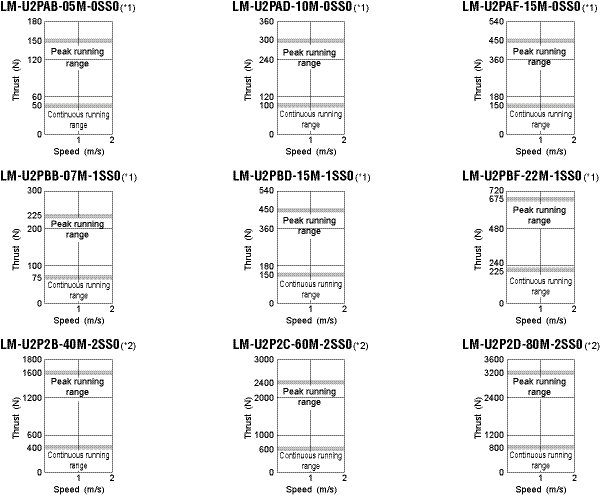
Linear Servomotor Model LM-U2 |
PAB-05M-0SS0 |
PAD-10M-0SS0 |
PAF-15M-0SS0 |
PBB-07M-1SS0 |
PBD-15M-1SS0 |
PBF-22M-1SS0 |
P2B-40M-2SS0 |
P2C-60M-2SS0 |
P2D-80M-2SS0 | |
|
Compatible Amplifier MR-J3- |
20B-
|
40B-
|
40B-
|
20B-
|
60B-
|
70B-
|
200B-
|
350B-
|
500B-
| |
|
Power Facility Capacity (kVA) |
0.5 |
0.9 |
0.9 |
0.5 |
1.0 |
1.3 |
3.5 |
5.5 |
7.5 | |
|
Cooling Method |
Self-cooling | |||||||||
|
Thrust |
Continuous (N) |
50 |
100 |
150 |
75 |
150 |
225 |
400 |
600 |
800 |
|
Maximum (N) |
150 |
300 |
450 |
225 |
450 |
675 |
1600 |
2400 |
3200 | |
|
Maximum Speed (m/s) (*1) |
2.0 | |||||||||
|
Magnetic Attraction Force (N) |
0 | |||||||||
|
Weight kg (lb) |
Primary Side (Coil) |
0.3 (0.67) |
0.6 (1.4) |
0.8 (1.8) |
0.4 (0.89) |
0.8 (1.8) |
1.1 (2.5) |
2.9 (6.4) |
4.2 (9.3) |
5.5 (13) |
|
Secondary Side (Magnet) |
240mm / piece: 2.0 (4.4)
|
240mm / piece: 2.6 (5.8)
|
300mm / piece: 9.6 (22)
| |||||||
|
Secondary Side Model LM-U2 |
SA0-_-0SS0 |
SB0-_-1SS0 |
S20-_-2SS0 | |||||||
|
Recommended Load / Motor Mass Ratio |
Maximum of 30 times the mass of the linear servomotor’s primary side | |||||||||
|
Structure |
Open (protection level: IP00) | |||||||||
|
Environment |
Ambient Temperature |
0 to 40°C (32 to 104°F) (non-freezing), storage: -15 to 70°C (5 to 158°F) (non-freezing) | ||||||||
|
Ambient Humidity |
80% RH maximum (non-condensing), storage: 90% RH maximum (non-condensing) | |||||||||
|
Atmosphere |
Indoors (no direct sunlight); no corrosive gas, inflammable gas, oil mist or dust | |||||||||
|
Vibration |
49m/s² maximum | |||||||||
|
Elevation |
1000m or less above sea level | |||||||||
Notes:
- The linear servomotor’s maximum speed or linear encoder’s rated speed, whichever is smaller, is the upper limit value of the linear servomotor’s speed.
Notes:
- For 3-phase 200VAC or 1-phase 230VAC.
- For 3-phase 200VAC.
|
Linear Encoder Type |
Manufacturer |
Model |
Resolution |
Rated Speed (*3) |
Effective Measurement Length (Maximum) |
Communication Method |
Position System | |
|
Mitsubishi Serial Interface Compatible |
Absolute Type |
Mitutoyo Corporation |
AT343A |
0.05µm |
2.0m/s |
3000mm |
2-wire type |
Absolute |
|
AT543A-SC |
2.5m/s |
2200mm | ||||||
|
ST741A |
0.5µm |
4.0m/s |
6000mm | |||||
|
ST743A (*7) |
0.1µm | |||||||
|
Heidenhain Corporation |
LC491M |
0.05µm/ 0.01µm |
2.0m/s |
2040mm |
4-wire type | |||
|
LC192M |
3.0m/s |
4240mm | ||||||
|
Incremental Type |
Sony Manufacturing Systems Corporation |
SL710+PL101-R/RH
|
0.2µm (*4) |
6.4m/s |
3000mm |
2-wire type |
Incremental | |
|
SH13
|
0.005µm (*4) |
1.4m/s |
1240mm | |||||
|
Renishaw Inc. |
RGH26P |
5µm |
4.0m/s |
70000mm | ||||
|
RGH26Q |
1µm |
3.2m/s | ||||||
|
RGH26R |
0.5µm |
1.6m/s | ||||||
|
Heidenhain Corporation |
LIDA485+APE391M |
0.005µm (20/4096µm) |
4.0m/s |
30040mm |
4-wire type | |||
|
LIDA487+APE391M |
6040mm | |||||||
|
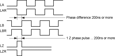
ABZ Phase Differential Output Type (*5) |
Incremental Type |
Not designated |
- |
Within tolerable resolution range (*6) |
Depends on linear encoder |
Depends on linear encoder |
Differential 3-pair type | |
Notes:
- Consult with the relevant linear encoder manufacturer for details on the linear encoder’s working environment and specifications.
- The linear servomotor generates heat. Take the linear encoder’s working environment temperature into consideration when configuring the system.
- The indicated values are the linear encoder’s rated speed when used in combination with the Mitsubishi linear compatible servo amplifier. The values may differ from each manufacturer’s specifications. The linear servomotor’s maximum speed or linear encoder’s rated speed, whichever is smaller, is the upper limit value of the linear servomotor’s speed.
- The resolution varies according to the setting value of the interpolator, MJ830/MJ831 manufactured by Sony Manufacturing Systems Corporation. Set the resolution between the minimum resolution and 5mm.
- Output the A-phase, B-phase and Z-phase signals in the differential line driver. The phase difference of A-phase pulse and B-phase pulse, and the width of Z-phase pulse must be 200ns or wider. Home position return is not possible with a linear encoder which is not equipped with a Z-phase.
- The tolerable resolution range is 0.005 to 5mm. Select the linear encoder within this range.
- Servo amplifier with software version A1 or above is compatible with this linear scale.
Notes:
- Setup software MR- Configurator Software version 5.00A or above is planned to be compatible with MR-J3-_B-RJ004U_. Refer to the following for software versions of Q172HCPU and Q173HCPU compatible with linear servo LM Series.
• Q172HCPU, Q173HCPU OS software (SW6RN-SV13MM /-SV22MM) Software version: 00D or above
• Integrated start-up support software MT Developer (SW6RNC-GSVPROE/-GSVSETE) Software version: 00N or above - The linear encoder, linear encoder head cable and encoder cable are not enclosed with the purchased linear servomotor and must be prepared by the user.
- Use the recommended linear encoder manufacturer's products for the linear encoder and linear encoder head cable.
- Consult with the linear encoder manufacturer regarding the working environment and specifications, and select the proper products.
• Cautions regarding the linear encoders
• Linear encoder, head cable and encoder cable are not supplied with the linear servomotor.
• Linear encoder and head cable, manufactured by the recommended manufacturers, must be used.
• Consult relevant manufacturers for details on linear encoder’s working environment and specifications.
MR-J3 Linear Servo Cables and Connectors
|
Item |
Model |
Stocked Lengths (Meters) |
Protection Level |
Diagram | |
|
|
CN2 or CN2L Connector |
MR-J3CN2 |
S |
IP20 |
|
|
|
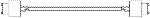
CN2 or CN2L Cable |
MR-EKCBL_M-H
|
2, 5, 10 |
IP20 |
|
|
|
CN2 or CN2L Connector Set |
MR-ECNM |
S |
IP20 |
|
|
|
CNP1 Connector 1kW or less (comes with J3 Amp standard) |
54928-0670 |
S |
- |
|
|
CNP1 Connector 2kW - 3.5kW (comes with J3 Amp standard) |
PC4/6-STF-7.62 |
S |
- | ||
|
|
CNP2 Connector up to 3.5kW (comes with J3 Amp standard) |
54927-0510 |
S |
- |
|
|
|
CNP3 Connector 1kW or less (comes with J3 Amp standard) |
54928-0370 |
S |
- |
|
|
CNP3 Connector 2kW - 3.5kW (comes with J3 Amp standard) |
PC4/3-STF-7.62 |
S |
- | ||
|
|
CNP1-2-3 Insertion Tool (comes with J3 Amp standard) |
54932-0000 |
S |
- |
|
|
|
SSCNETIII Cable (standard cord for inside panel) |
MR-J3BUS_M (_ = cable length 0.15, 0.3, 0.5, 1, 3m) |
015, 03, 05, 1, 3 |
- |
|
|
|
SSCNETIII Cable (standard cable for outside panel) |
MR-J3BUS_M-A (_ = cable length 5, 10, 20m) |
5, 10, 20 |
- | |
|
|
SSCNETIII Cable (long distance cable) |
MR-J3BUS_M-B
|
30 |
- |
|
|
|
Connector Cap for SSCNETIII |
Connector comes with amplifier standard |
- |
- |
|
|
|
Personal Computer Communication Cable USB Cable |
MR-J3USBCBL3M (cable length 3m) |
S |
- |
|
|
|
CN10 or CN3 Signal Connector (20 pin) |
MR-J2CN1 |
S |
- |
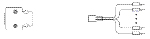
|
|
|
CN10 or CN3 Pigtail Cable (20 pin) |
MR-CCN1CBL-_M
|
3, 5 |
- |
|
|
|
20 Pin Terminal B Lock for J3-B (TB20 cannot be used) |
PS7DW-20V14B-F |
S |
- |
|
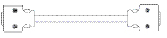
|
|
Cable for PS7DW-20V14B-F Terminal Block |
MR-J2HBUS_M (_ = cable length 0.5, 1, 3, 5m) |
05, 1, 3, 5 |
- |
|


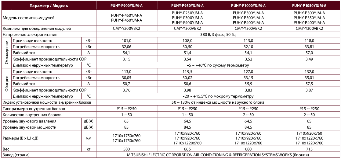
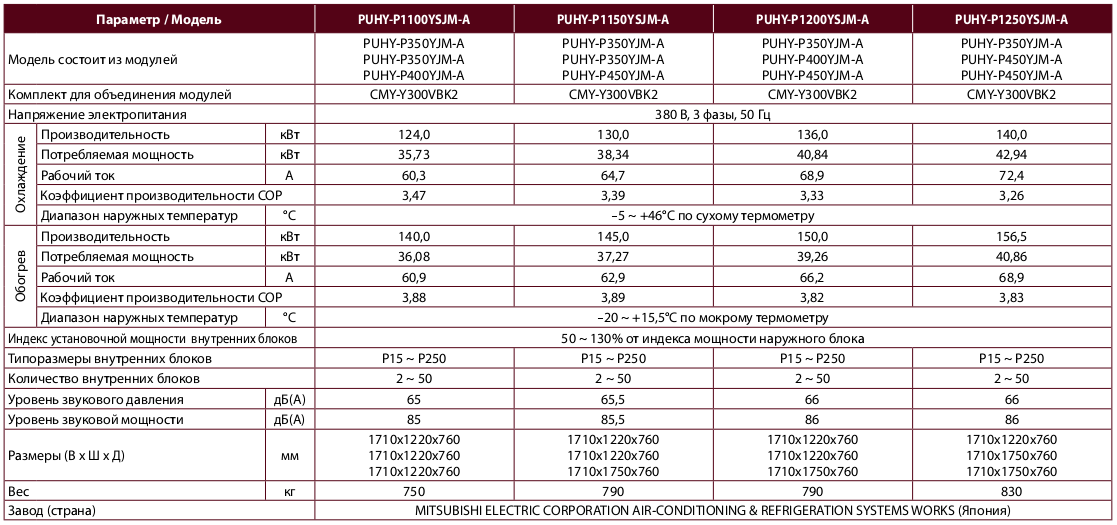
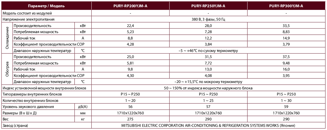
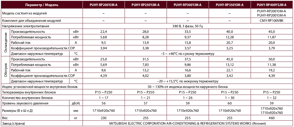
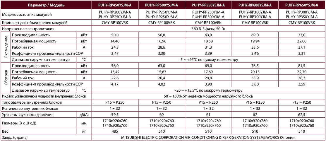
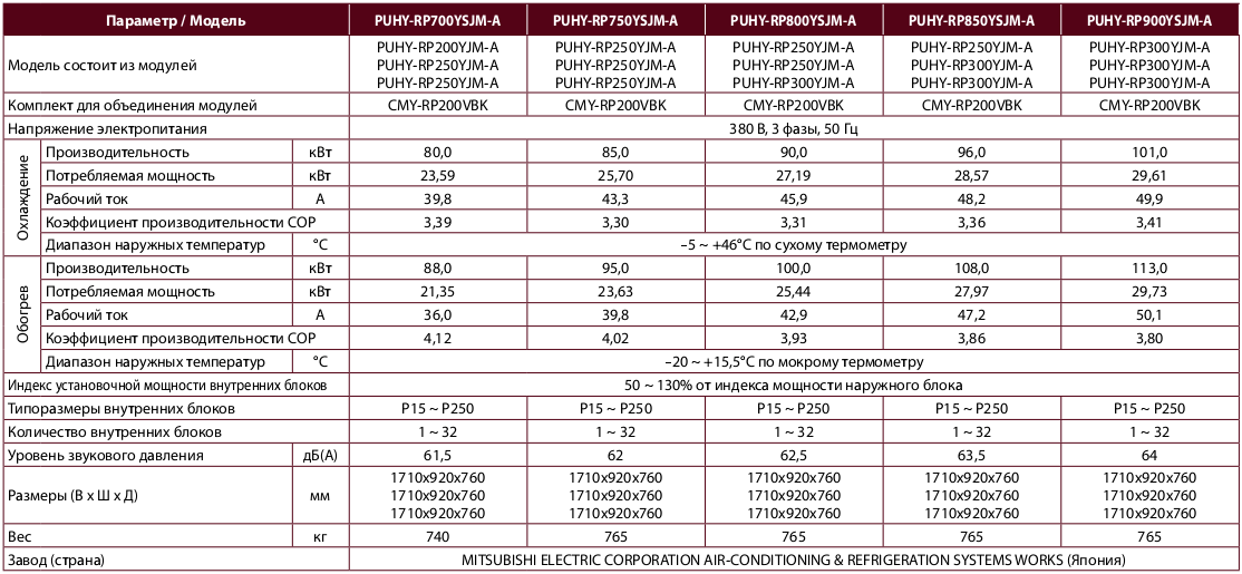
Характеристики PUHY-RP, PURY-RP
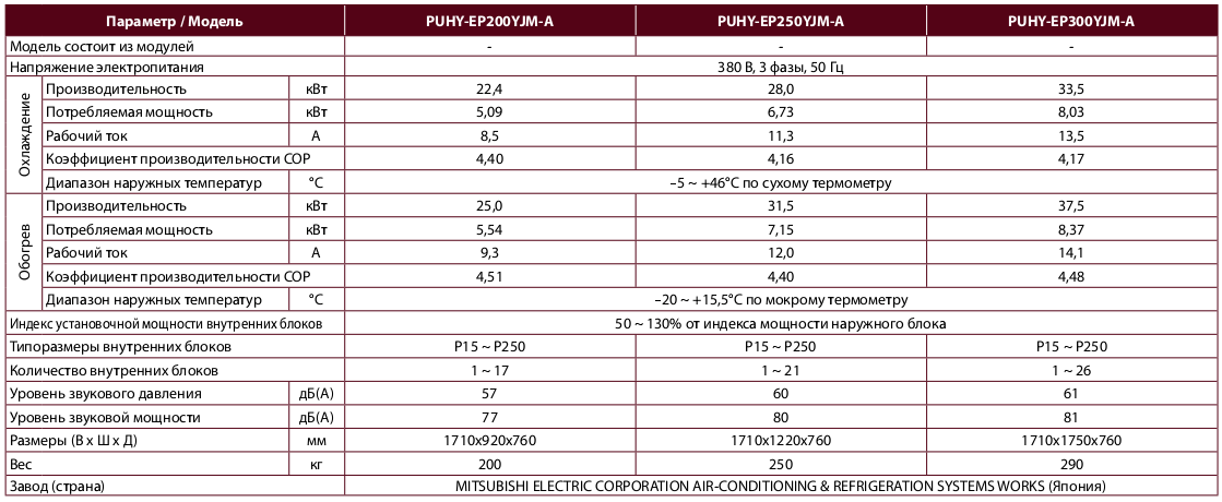
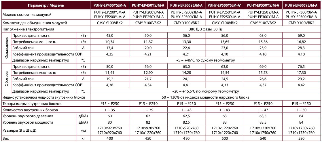
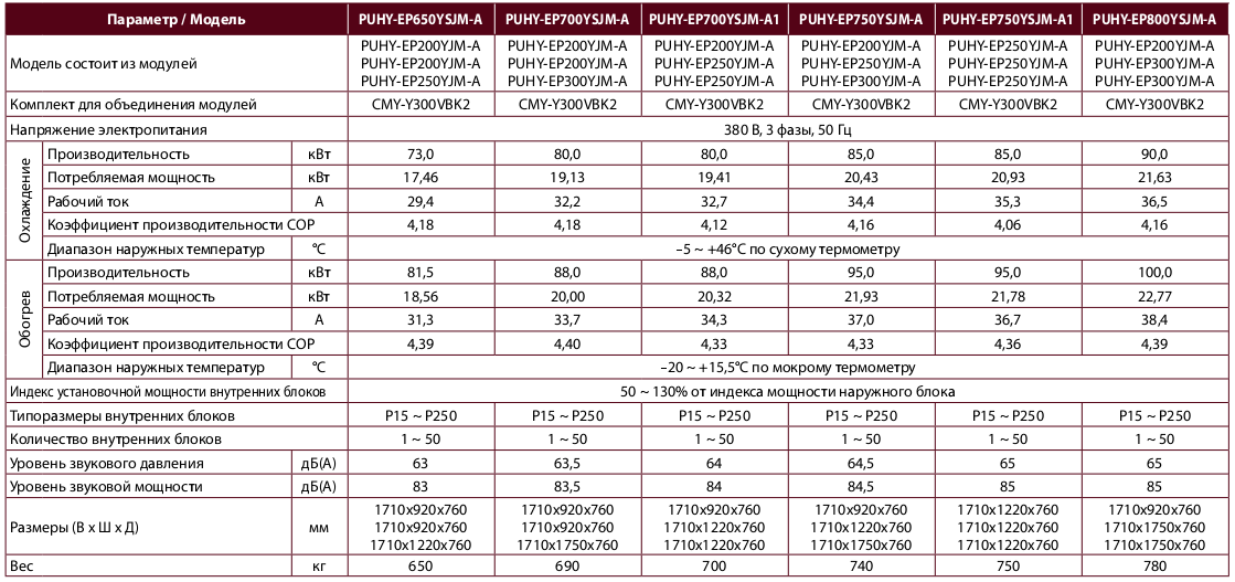
Replace R2 (22,4 - 33,5 кВт)
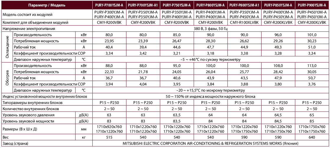
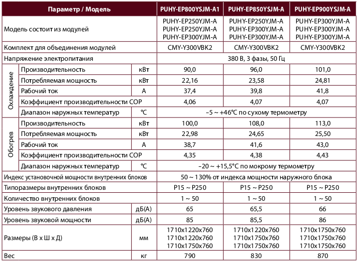
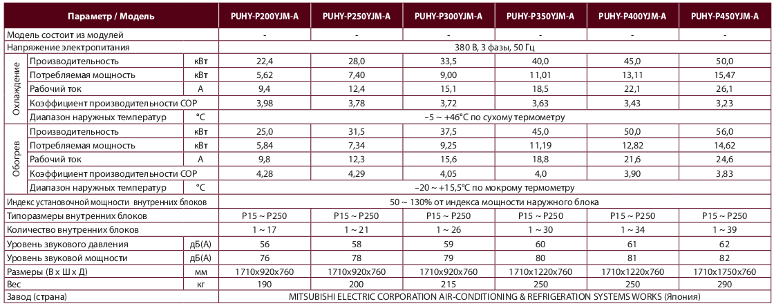
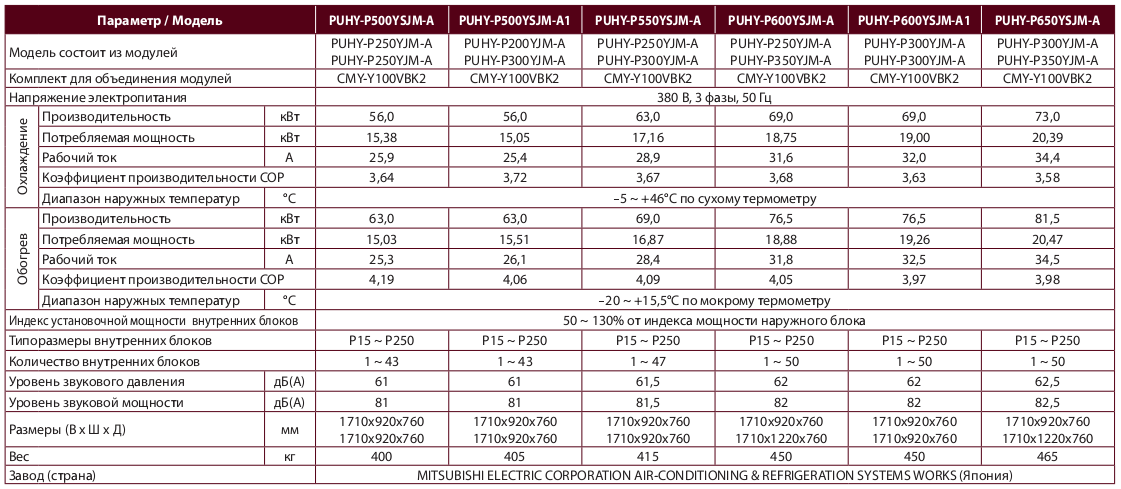
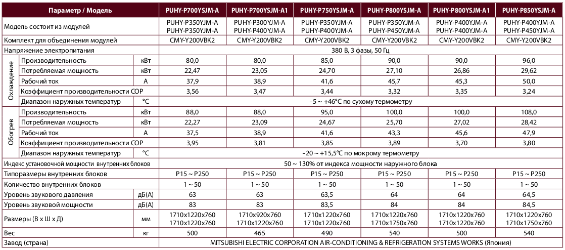
Replace Y (22,4 - 101,0 кВт)
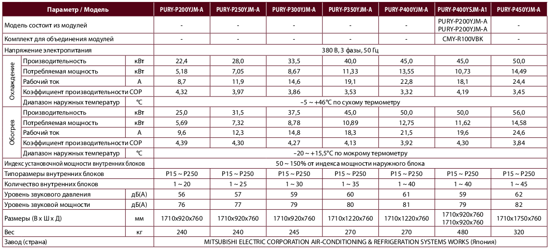
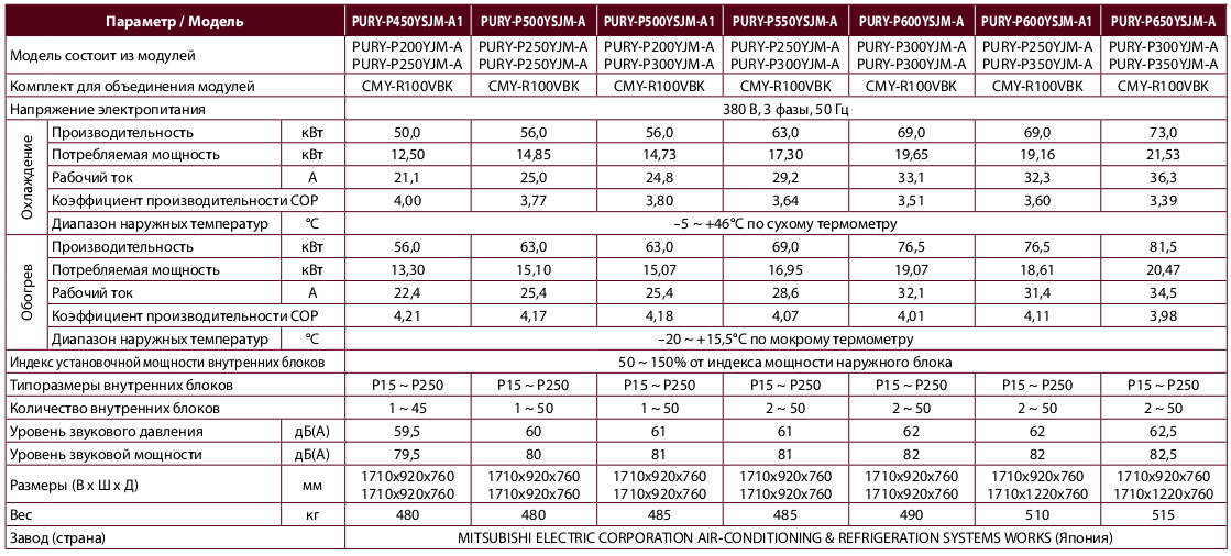
Характеристики PQRY-P YHM
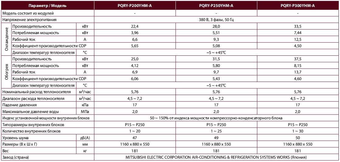
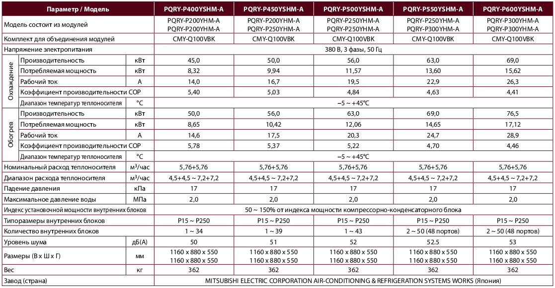
Примечания
- Для работы компрессорно-конденсаторного агрегата при температуре теплоносителя от −5°С до +10°С необходимо установить DIP-переключатель на плате управления агрегата в положение ON (перед включением электропитания).
- При температуре теплоносителя от −5°С до +10°С в теплоноситель необходимо добавить антифриз. Допускается применение этиленгликоля или пропиленгликоля.
- Компрессорно-конденсаторный агрегат должен быть установлен в помещении, в котором температура воздуха не превышает 40°С, а относительная влажность — 80%.
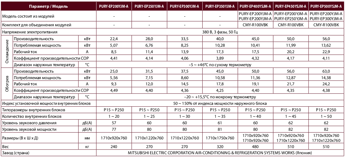
Характеристики PQHY-P YHM
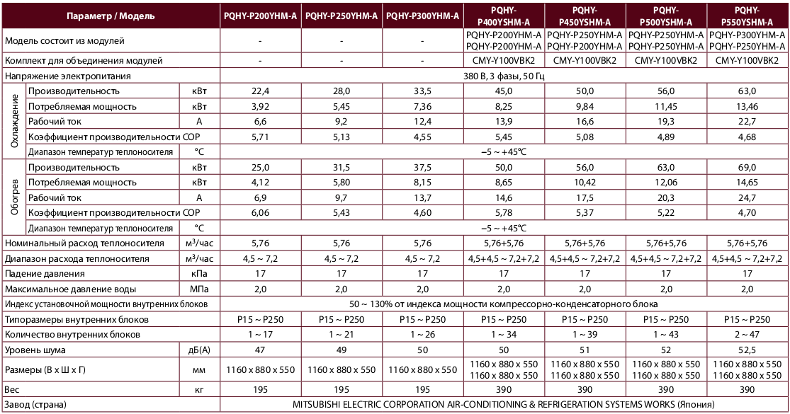
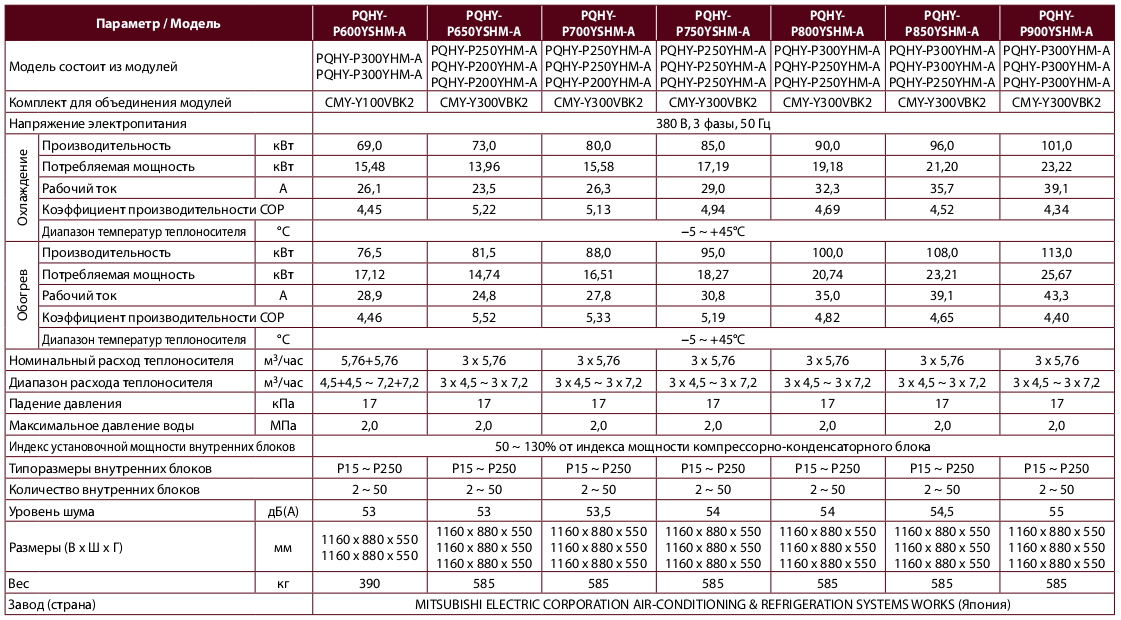
Примечания:
- Для работы компрессорно-конденсаторного агрегата при температуре теплоносителя от −5°С до +10°С необходимо установить DIP-переключатель на плате управления агрегата в положение ON (перед включением электропитания).
- При температуре теплоносителя от −5°С до +10°С в теплоноситель необходимо добавить антифриз. Допускается применение этиленгликоля или пропиленгликоля.
- Компрессорно-конденсаторный агрегат должен быть установлен в помещении, в котором температура воздуха не превышает 40°С, а относительная влажность — 80%.
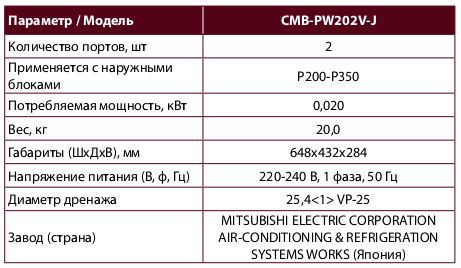
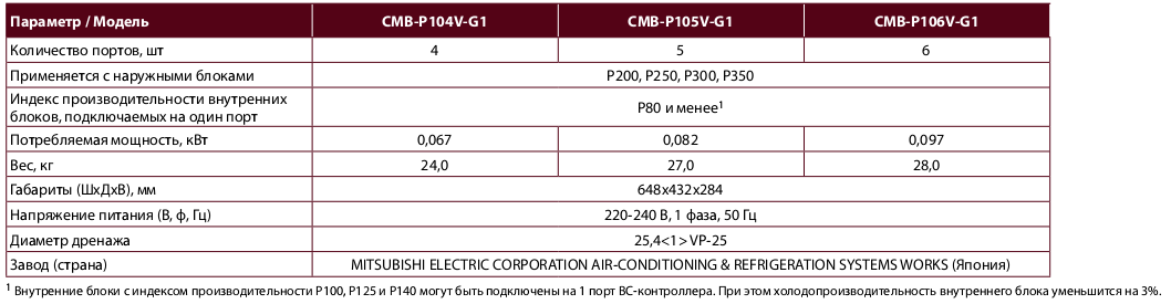
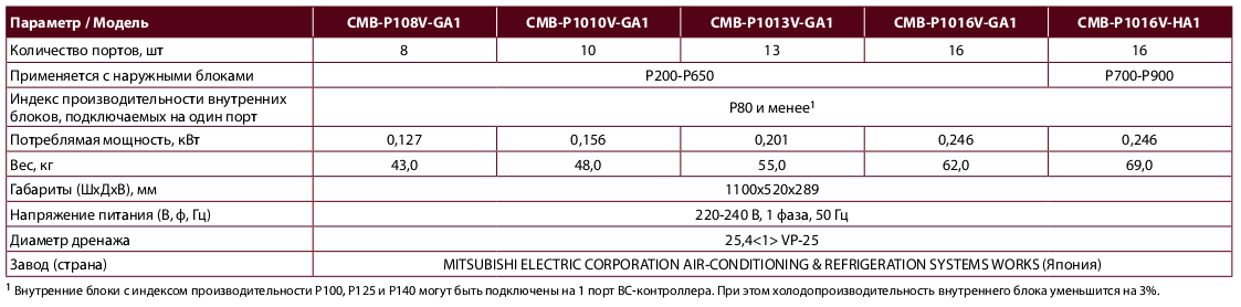
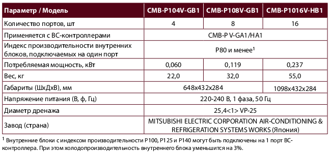
Характеристики CMB-P(W)
CMB-P V-G1
CMB-P V-GA1/HA1
CMB-P V-GB1/HB1
WCB-контроллер CMB-PW202V-J